Intro to FreeCAD Part 7: Sweeps and Lofts with Guide Curves
2025-02-06 | By ShawnHymel
In the world of 3D modeling, creating organic and curved shapes can be challenging, especially when the software lacks certain features out of the box. FreeCAD, while a powerful and versatile open-source CAD program, doesn't natively support guide rails for sweeps and lofts—a feature that can simplify the creation of complex, curved geometries. However, with a bit of ingenuity and the use of additional workbenches (plugins), you can achieve impressive results.
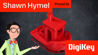
In this tutorial, we'll explore how to use B-splines and the Loft tool in FreeCAD to create organic shapes manually. We'll also introduce the Curved Shapes Workbench, a plugin that adds guide rail functionality, making the process more straightforward. As a practical example, we'll design a simple boat hull, demonstrating both manual and plugin-assisted methods.
Understanding B-Splines in FreeCAD
B-splines (Basis Splines) are mathematical representations of curves that allow for smooth and flexible modeling of complex shapes. In FreeCAD, B-splines enable you to create organic curves by manipulating control points and knots. They are essential for designing objects like boat hulls, car bodies, and any form requiring smooth, flowing lines. If you’d like to learn more, FreeCAD has an excellent article on B-Splines.
1. Designing a Boat Hull Manually
We'll start by manually creating a boat hull using B-splines and the Loft tool. This method involves creating several cross-sectional sketches (ribs) and lofting between them.
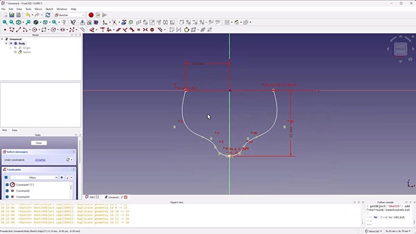
Creating the Stern Sketch
- Create a New Document and Body:
- Open FreeCAD and switch to the Part Design workbench.
- Click Create New Document and then Create Body.
- Sketch the Stern on the XZ Plane:
- Click Create Sketch and select the XZ plane.
- Use the B-spline tool to draw half of the stern profile:
- Start at the origin (to ensure symmetry).
- Click to add control points shaping the curve outward and upward.
- End the curve by connecting it back to the Z-axis.
- Mirror the B-spline across the Z-axis to complete the stern shape.
- Close the Sketch by connecting the endpoints, ensuring it's a closed profile.
- This is important! If the sketch is not fully closed, the loft tool will fail!
- Constraints and Adjustments:
- Feel free to apply e.g., width and height constraints.
- Optional: Fully constrain the sketch using dimensions for precision.
Defining Guide Rails
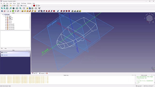
- Sketch the Boat Outline on the XY Plane:
- Create a new sketch on the XY plane.
- Bring in external geometry from the stern and bow sketches.
- Use the B-spline tool to draw the boat's outline from stern to bow.
- Mirror the B-spline across the Y-axis for symmetry.
- Sketch the Side Profile on the YZ Plane:
- Create another sketch on the YZ plane.
- Bring in external geometry from the stern and bow.
- Draw a B-spline representing the side elevation of the hull.
- Add a straight line at the base for the keel.
- Ensure tangency between the B-spline and the keel line for smoothness.

Creating Rib Sketches
- Copy and Adjust the Stern Sketch:
- Copy the stern sketch and paste it as a new sketch.
- Position it along the boat's length (e.g., at -15mm, 0mm, 15mm, 25mm).
- Modify the B-spline control points in each sketch to match the desired hull shape at that section.
- Align the sketches with the guide rails by adjusting control points.
- Ensure Closed Profiles:
- For each rib sketch, ensure that all lines and curves form a closed shape. The Loft tool will fail if any of the sketches are not fully closed. Use the Coincident Constraint to connect endpoints.
Lofting the Hull
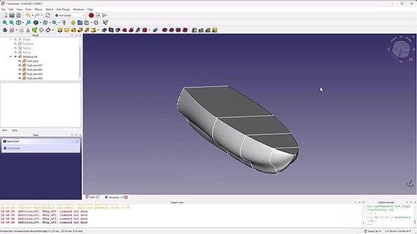
- Select the Rib Sketches in Order:
- Hold Ctrl and select the sketches from stern to bow in sequence.
- Apply the Loft Tool:
- Click on the Loft icon in the Part Design workbench.
- In the Loft dialog:
- Ensure Ruled Surface is unchecked for smooth/curved transitions.
- Verify that the sketches are ordered correctly.
- Finalize the Loft:
- Click OK to generate the lofted hull.
- Hide the sketches to view the hull without distractions.
2. Using the Curved Shapes Workbench
While the manual method works and offers more control, it can be time-consuming. The Curved Shapes Workbench plugin simplifies the process by allowing you to use guide rails for lofting by creating multiple copies of a cross-section sketch (ribbing).
Installing the Plugin
- Access the Add-on Manager:
- Go to Tools > Add-on Manager.
- Install the Curved Shapes Workbench:
- Search for "Curved Shapes" in the workbenches list.
- Click Install and wait for the installation to complete.
- Restart FreeCAD to activate the new workbench.

Creating the Hull with Guide Rails
- Switch to the Curved Shapes Workbench:
- Select Curved Shapes from the workbench dropdown menu.
- Prepare the Base Sketch and Guide Rails:
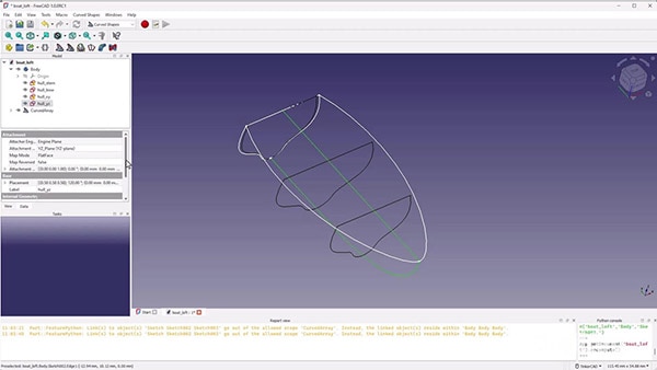
- Ensure you have the initial stern sketch and the guide rails (XY and YZ planes).
- Use the Curved Array Tool:
- Click on the Curved Array icon.
- If you do not see your Base sketch (cross-section) copied, ensure that you have both top and bottom guide rail sketches defined for both guide rail planes.
- In the properties panel:
- Base: Select the stern sketch.
- Hole Curves: Select the guide rails (both the XY and YZ sketches).
- Adjust the Array:
- Increase the Number of Items to improve resolution (e.g., 30).
- Set Solid to True to create a solid object.
- Finalize the Hull:
- Hide the original sketches to view the generated hull.
- The Curved Array tool automatically lofts the base sketch along the guide rails, creating a smooth hull shape.

3. Hollowing the Hull
To make the hull suitable for 3D printing (and to ensure it floats), we'll hollow it out.
- Clone and Scale the Hull:
- Switch to the Draft workbench.
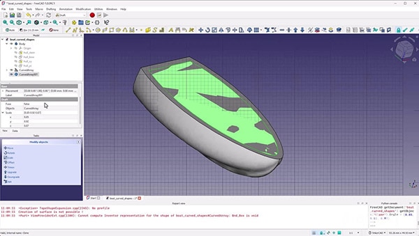
- Select the hull and click Clone.
- In the clone's properties:
- Adjust the Scale factors slightly less than 1 (e.g., 0.90) in X, Y, and Z to create an inner hull.
- Create a Cut:
- Switch to the Part workbench.
- Use the Boolean Cut tool to subtract the inner hull from the outer hull.
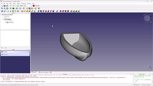
- This results in a hollowed hull with uniform wall thickness.
- Create BaseFeature
- Switch to the Part Design workbench.
- Create a new Body.
- Drag the Cut part into the new Body in the Tree View.
- This creates a Part Design Body out of the shell that we made so that you can add other features to it.
4. 3D Printing the Boat
- Export the Hull:
- Select the final hull model.
- Go to File > Export and choose the STL format.
- Prepare for Printing:
- Import the STL file into your slicing software (e.g., Cura, PrusaSlicer).
- Orient the boat for optimal printing (e.g., upside down to minimize support inside the hull).
- Configure print settings:
- Layer height: 0.1mm for fine details.
- Infill: Low percentage since the hull is hollow.
- Supports: Enable as necessary.
- Print the Boat:
- Start the print and monitor for any issues.
- Once printed, remove supports carefully.
- Test the Boat:
- Place it in water to see if it floats.
- Enjoy your custom-designed boat!

Challenge: Designing a Propeller
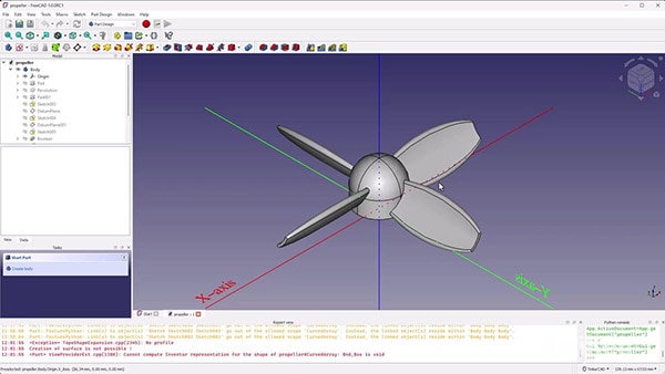
As a final challenge, apply your newfound skills to design a propeller. Propellers require complex, curved blades that can be crafted using B-splines, lofts, and sweeps.
Tips:
- Create the Blade Profile:
- Sketch the blade's cross-section using B-splines.
- Use the Sweep tool to extend the profile along a helical path for a twisted blade.
- Use Polar Patterns:
- After creating one blade, use the Polar Pattern feature to replicate it around the propeller's central axis.
- Consider Blade Angle:
- Adjust the twist and pitch of the blades to mimic real propeller designs.
- 3D Print and Test:
- Export the model and print it.
- Attach it to a small motor to see it in action.
Conclusion
Creating organic and complex shapes in FreeCAD may seem daunting at first, especially without built-in guide rail functionality. However, by mastering B-splines and utilizing plugins like the Curved Shapes Workbench, you can expand FreeCAD's capabilities significantly.
Through this tutorial, we've learned how to:
- Manually create a boat hull using B-splines and lofts.
- Install and use the Curved Shapes Workbench to simplify the process.
- Hollow out a model for 3D printing.
- Apply these techniques to design other complex objects like propellers.
We encourage you to share your designs or printed models on social media platforms. Use the hashtag #DKFreeCAD and tag @DigiKey to showcase your creations and connect with the community.
In the next episode, we'll delve into even more advanced features, exploring the Curves Workbench and other tools for creating intricate designs.


