制造商零件编号 5096
TERMINAL BLOCK BREAKOUT RPI PICO
Adafruit Industries LLC
License: See Original Project 3D Printing Qwiic Raspberry Pi MCU STEMMA
For my 100th video milestone, I handed creative control over to you, the Byte Sized Engineering community. The challenge was to come up with a mystery project that I had to build, sight unseen. Everyone knew the plan except for me. A box from DigiKey arrived with electronics and a single clue: build some sort of game - no rules, no schematics, and no instructions.
After days of mounting confusion and failed ideas, I called the only two people who knew the plan, Ian and Jonathan, but they didn't provide me with answers; instead, they gave me more riddles. The call was coming to an end, and I was getting frustratingly little information.
Let's jump back into that call, right where the fog finally starts to lift...
Okay, we were talking about the conduit and the hinge. “What if I make two sets of conduit that hinge together at the top? Am I making a pyramid?" I asked.
Ian's face lit up. "I think it would be more fun if it were like a pyramid," said Jonathan.
Just like that, the pieces began to fall into place. This isn't just a game; it's like a pong/pinball battle. Left and right. If my opponent serves the "ping pong pixel" down my left conduit, I have to hit my left paddle and the power-ups! "Power Up makes it go faster," I brainstormed. "The speed of the ball has to like... power up, and it just shoots it across the net!"
That phone call was exactly what I needed. It gave me just enough to get moving.
"Can't wait to see what you come up with," Jonathan said. "We like to make you suffer." Ian added, “Yeah, it's been worth it.”
With a clear direction, the first step was to model this on the computer. I needed to design, and 3D print some couplers to connect the metal conduit to the central hinge. After the first print, it was time for a test fit. One side was a little tight, but the other slid on way easier. Let's see how it stands… Oh. That’s very wobbly. And that broke. Well, the first prototype is a failure, but this gives me a real sense of what this will look like, and I'm excited. The solution is actually quite simple. I need to add fillets to the design to increase the part's strength. Back to the 3D printer to print the next version…
While those parts were being reprinted, I had some time to think. I loved the community's pyramid idea, but I had another thought I wanted to explore. What if, instead of a rigid pyramid, the pathway for the LEDs was a graceful arch? I think the curvature of an arch would be more visually interesting. To create the arches, I'm thinking of something flexible, such as vinyl tubing or thin PVC pipe. While browsing around, I came across PEX tubing, the type used for plumbing. It's strong but flexible. By the time I got home, the new, stronger couplers were done printing. And they look awesome! But now I was conflicted. Do I stick with the original pyramid, or go with my new arch idea?
After clearing off my design canvas (it seems our top-secret design was infiltrated by my kids), I decided to go for the arch. My new plan: use the metal conduit as a square base, and then use the flexible PEX tubing to create two opposing arches, much like setting up a tent. This required designing new corner pieces to hold both the conduit and the PEX tubing. Let's get printing.
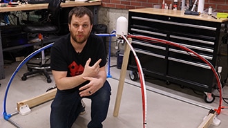
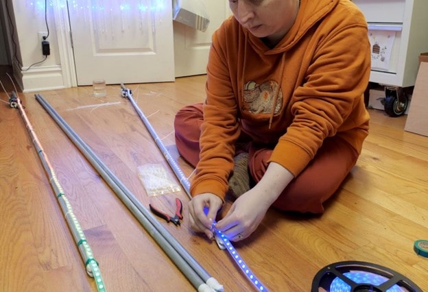
Assembling the frame was a real "whoa" moment. It's one thing to model something on the computer; it's an entirely different thing to build it in real life. This is a lot bigger than I realized. I got two colors of PEX tubing, red and blue, since this is a two-player game. Red player versus blue player sounds pretty cool. Next, I assemble the arches. It really is like putting up a camping tent (and so much easier when your dad's not yelling at you).
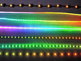
Now, I need to attach the LED strips to the PEX pipes using zip ties and then start writing some test code to see if this thing lights up. It works! That looks great!
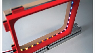
As I move to the next step, I wonder how to mount those massive push buttons? I decided to use the 2x4s as a base for the player control panels. I laser-cut a top plate with holes for the buttons and labels for Left, Right, Swap, and Power Up. After I cut the main LED strips for the arches, I had about a meter of leftover LEDs from each string. This is perfect, I’ll use this for the Power Up meter.
So, let's recap the game mechanics of Pixel Ball:
It's a hybrid of Pong and Pinball. A pixel volleys back and forth over the arches between the Red and Blue players.
Players use their Left and Right buttons to "return" the pixel when it reaches their side.
Holding the Swap button while returning a volley changes the pixel's trajectory, making it harder for your opponent.
Successfully returning serves fills your Power Up meter. Once full, you can hit the Power Up button to launch the pixel back at super-speed!
For the button layout, I put the Left/Right buttons where my dominant hand would be, with Swap easily accessible next to them. Power Up is on the far side.
It was time to tackle the wiring. To save on wire, I decided to run a ground bus for all the buttons and their internal LEDs, minimizing the number of wires that need to run back to the control board. The real challenge was hiding all the wires. I decided to utilize the space inside the conduit and the PEX tubing and routed them through. So clean!
After a very busy weekend working on the project, all eight buttons, their internal LEDs, and the four RGB LED strips were wired up to a central point. Now, I needed to connect it all to the control board, which features the Raspberry Pi RP2040 microcontroller.
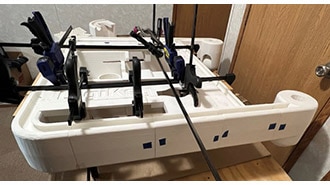
I designed a 3D-printed capsule to house the board and wiring at the top of the arches. But, of course, I hit a snag. The control board wouldn't fit inside my first print! I forgot to add a slot for the board to slide through the threads, and I didn't account for the height of the solder joints; I simply used the standard PCB height of 1.6mm in my model. Classic mistake. So, I went back to the computer to fix the design and print another one. After a ton of work, it's all wired up. Time to write some more test code to make sure every button and every LED works as it should. We are in the homestretch.
Next week, in the final part of this series, I will put the finishing touches on this project. You're going to witness the inaugural Pixel Ball World Championship (okay, it might just be me and Cameraman Pat). And most importantly, we'll answer the question: Did I use all the components and fulfill my promise to you?