制造商零件编号 ESP32-S3-DEVKITC-1-N32R8V
ESP32-S3-WROOM-2-N32R8V DEV BRD
Espressif Systems
Multithreading is a critical feature in real-time operating systems (RTOS) like Zephyr, enabling developers to execute multiple tasks concurrently. By leveraging multiple threads, you can structure your embedded applications to perform tasks like handling inputs, processing data, and controlling outputs independently, all while ensuring that the system remains responsive and efficient.
In this post, we'll explore the basics of multithreading in Zephyr RTOS through a simple example program. The program demonstrates how to blink an LED and print messages to the console simultaneously by creating and managing threads. By the end of this post, you'll understand how threads work in Zephyr, how to define and configure them, and how to manage their execution.
All code for this Introduction to Zephyr series can be found here: https://github.com/ShawnHymel/introduction-to-zephyr
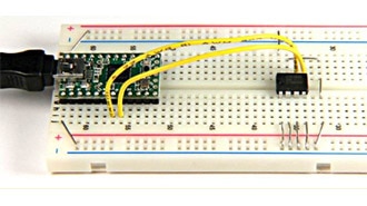
For this demonstration, we will connect an LED to pin 13 on the ESP32-S3-DevKitC. Here is a Fritzing diagram showing all of the connections we will use throughout this series:

We will take our simple blink application and divide up the separate activities (blinking LED, printing to the console) into different threads. While this is a trivial example, it shows how to run a separate, concurrent threads in Zephyr.
Create a new project directory structure:
/workspace/apps/08_demo_multithreading/
├─ boards/
│  └─ esp32s3_devkitc.overlay
├─ src/
│  └─ main.c
├─ CMakeLists.txt
└─ prj.conf
We will use the same boilerplate CMakeLists.txt file that we’ve been using for most of the series:
cmake_minimum_required(VERSION 3.22.0)
find_package(Zephyr REQUIRED HINTS $ENV{ZEPHYR_BASE})
project(button_demo)
target_sources(app PRIVATE src/main.c)
prj.conf
Leave empty.
We will use the same overlay file that we had in the first tutorial. It simply assigns pin 13 as an output pin and gives it the alias “my-led.”
/ {
    aliases {
        my-led = &led0;
    };

    leds {
        compatible = "gpio-leds";
        led0: d13 {
            gpios = <&gpio0 13 GPIO_ACTIVE_HIGH>;
        };
    };
};
Here is the complete code for reference:
#include <stdio.h>
#include <zephyr/kernel.h>
#include <zephyr/drivers/gpio.h>
// Sleep settings
static const int32_t blink_sleep_ms = 500;
static const int32_t print_sleep_ms = 700;
// Stack size settings
#define BLINK_THREAD_STACK_SIZE 256
// Define stack areas for the threads
K_THREAD_STACK_DEFINE(blink_stack, BLINK_THREAD_STACK_SIZE);
// Declare thread data structs
static struct k_thread blink_thread;
// Get LED struct from Devicetree
const struct gpio_dt_spec led = GPIO_DT_SPEC_GET(DT_ALIAS(my_led), gpios);
// Blink thread entry point
void blink_thread_start(void *arg_1, void *arg_2, void *arg_3)
{
int ret;
int state = 0;
while (1) {
// Change the state of the pin
state = !state;
// Set pin state
ret = gpio_pin_set_dt(&led, state);
if (ret < 0) {
printk("Error: could not toggle pin\r\n");
}
k_msleep(blink_sleep_ms);
}
}
int main(void)
{
int ret;
k_tid_t blink_tid;
// Make sure that the GPIO was initialized
if (!gpio_is_ready_dt(&led)) {
printk("Error: GPIO pin not ready\r\n");
return 0;
}
// Set the GPIO as output
ret = gpio_pin_configure_dt(&led, GPIO_OUTPUT);
if (ret < 0) {
printk("Error: Could not configure GPIO\r\n");
return 0;
}
// Start the blink thread
blink_tid = k_thread_create(&blink_thread, // Thread struct
blink_stack, // Stack
K_THREAD_STACK_SIZEOF(blink_stack),
blink_thread_start, // Entry point
NULL, // arg_1
NULL, // arg_2
NULL, // arg_3
7, // Priority
0, // Options
K_NO_WAIT); // Delay
// Do forever
while (1) {
printk("Hello\r\n");
k_msleep(print_sleep_ms);
}
return 0;
}
In the Docker container, build the demo application:
cd /workspace/apps/08_demo_multithreading/ west build -p always -b esp32s3_devkitc/esp32s3/procpu -- -DDTC_OVERLAY_FILE=boards/esp32s3_devkitc.overlay
On your host computer, flash the application (replace
python -m esptool --port "<PORT>" --chip auto --baud 921600 --before default_reset --after hard_reset write_flash -u --flash_size detect 0x0 workspace/apps/08_multithreading_demo/build/zephyr/zephyr.bin
After flashing completes, open a serial port:
python -m serial.tools.miniterm "<PORT>" 115200
You should see the LED flashing on the board as well as “Hello” being printed to the terminal.

In Zephyr, each thread requires its own stack for storing local variables, function call data, and more. The K_THREAD_STACK_DEFINE macro is used to allocate memory for the stack of the blink_thread:
#define BLINK_THREAD_STACK_SIZE 256 K_THREAD_STACK_DEFINE(blink_stack, BLINK_THREAD_STACK_SIZE);
Here, BLINK_THREAD_STACK_SIZE specifies the size of the stack (in bytes). The stack size should be chosen carefully based on the memory requirements of the thread.
Zephyr uses a k_thread structure to manage thread information, such as its state, priority, and stack pointer. In the program, we declare a k_thread instance for the blink thread:
static struct k_thread blink_thread;
As we saw in the first tutorial, the GPIO pin for the LED is defined using the Devicetree specification:
const struct gpio_dt_spec led = GPIO_DT_SPEC_GET(DT_ALIAS(my_led), gpios);
The GPIO_DT_SPEC_GET macro retrieves the GPIO device and pin information from the Devicetree alias my_led. This abstraction makes the code portable across different boards with varying GPIO configurations.
Before using the GPIO, the program ensures it is ready and configures it as an output pin:
const struct gpio_dt_spec led = GPIO_DT_SPEC_GET(DT_ALIAS(my_led), gpios);const struct gpio_dt_spec led = GPIO_DT_SPEC_GET(DT_ALIAS(my_led), gpios);const struct gpio_dt_spec led = GPIO_DT_SPEC_GET(DT_ALIAS(my_led), gpios);if (!gpio_is_ready_dt(&led)) {
printk("Error: GPIO pin not ready\r\n");
return 0;
}
ret = gpio_pin_configure_dt(&led, GPIO_OUTPUT);
if (ret < 0) {
printk("Error: Could not configure GPIO\r\n");
return 0;
}
The blink_thread_start function is the entry point for the blink thread. It toggles the state of the GPIO pin to blink the LED and sleeps for a specified duration:
void blink_thread_start(void *arg_1, void *arg_2, void *arg_3)
{
int ret;
int state = 0;
while (1) {
state = !state; // Toggle state
ret = gpio_pin_set_dt(&led, state);
if (ret < 0) {
printk("Error: could not toggle pin\r\n");
}
k_msleep(blink_sleep_ms); // Sleep
}
}
The k_msleep function suspends the thread for blink_sleep_ms milliseconds, allowing other threads to execute. Threads that are sleeping are considered to be “unready” in the “waiting state” (see here to read more about thread states).
The blink thread is created and started in the main function using the k_thread_create API:
blink_tid = k_thread_create(&blink_thread, // Thread struct blink_stack, // Stack K_THREAD_STACK_SIZEOF(blink_stack), blink_thread_start, // Entry point NULL, NULL, NULL, // Arguments 7, // Priority 0, // Options K_NO_WAIT); // Delay
You can find the Zephyr multithreading API documentation here.
The main function acts as the main thread. After configuring the GPIO and starting the blink thread, it enters an infinite loop that prints messages to the console and sleeps for print_sleep_ms milliseconds:
while (1) {
printk("Hello\r\n");
k_msleep(print_sleep_ms);
}
The main thread defaults to priority 0 (with preemption enabled) or -1 (with preemption disabled). While this example uses the main thread, you will often find many multithreaded applications simply sleep the main thread after spinning up its various worker threads.
Your challenge is to use a message queue to pass data between two threads. One thread should read from your temperature sensor (or other sensor), and the other thread should simply print the sensor value to the console. You can read about message queues here. You are welcome to use the MCP9808 I2C driver we made in lesson 6 or use the official JEDEC JC-42 driver to talk to the MCP9808 sensor (sample here).
My solution for this challenge is found here.
Zephyr RTOS offers robust support for multithreading, making it an excellent choice for building responsive and efficient embedded systems. Multithreading is incredibly useful when you need to handle multiple I/O events with latency, such as managing networking connections or responding to user interaction on an interface (graphical or text).
If you would like to dive more into real-time operating system theory (multithreading, queues, mutexes, semaphores, scheduling, etc.), check out our Introduction to RTOS series.
The following official Zephyr documentation can help you dive deeper into multithreading: