Power Supply and Topology Solutions for Driving LED Arrays
投稿人:电子产品
2014-02-25
Large numbers of LEDs, especially high-brightness LEDs (HB LEDs), are increasingly being used in a variety of array configurations for display backlighting, area illumination, and digital signage. While driving a single or even a few LEDs is fairly straightforward, doing so for these larger arrays brings issues of the overall LED interconnection topology, as well as options for powering and even controlling the array.
A single LED requires drive current between 20 and 60 mA, and has a voltage drop of 1.8 to 4 V (nominally 1.8 V for a red LED, moving up to 2.0 V for amber, 2.2 V for yellow, 3.5 V for green, 3.6 V for blue, and as high as 4.0 V for white). Driving LEDs means that designers must shift their thinking from the more-common voltage-sourcing supply to less-common, but equally viable current-sourcing (constant-current) supply or driver, and they are often less familiar with this power-supply mode and its implications.
The LED power-supply (see the TechZone article “How to Choose the Right Power Supply for Your LED Lighting Project”) and driver chain is conceptually simple (Figure 1). Driving the LEDs themselves is both easy and difficult. It is easy because they individually are a low/moderate current and voltage load, and the driver can operate at an efficient DC/DC conversion frequency, usually between 100 kHz and 1.5 MHz. However, it is difficult because the driver must act as a current source, not the more conventional voltage source, and this places new and sometimes difficult demands on its circuitry (and designers of the circuitry).

Figure 1: The LED driver in a multi-LED array configuration is the last stage in a power-supply chain that begins with the AC line (in most cases), goes through an optional lower-voltage DC/DC conversion stage, then provides final DC-voltage/current conversion and LED drive.
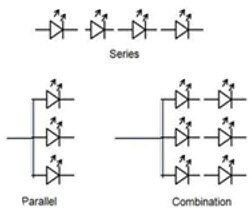
When using multiple LEDs, whether tens, hundreds, and even thousands of them, designers must first decide what combination of series, parallel, and series/parallel topology they want to use (Figure 2). Each choice brings trade-offs in driver options, cost, reliability, fault/failure handling, and physical layout options, which aggravates unavoidable dissipation and subsequent thermal considerations. (See also the TechZone article “Power Conversion Topology Critical for HB LED Designs”.)

Figure 2: Arrays of multiple LEDs can be wired as series-only, parallel-only, or as a combination of series and parallel. Each configuration brings different challenges to the LED driver and has different performance implications, which the designer must consider as part of system-level trade-offs.
In the serial configuration, all the LEDs are supplied by a single power rail. This means that the current through each LED is identical, which helps ensure (but does not guarantee) uniform output brightness (it also depends on how closely the LEDs are “binned” or selected). However, the open-mode failure of any single LED, which is the most-common failure mode, means the entire serial string goes dark. To avoid this problem, some designs add a special component around each LED that maintains current flow even if the LED opens, but this adds to cost and physical-space requirements.
The other problem with the serial configuration is compliance voltage. The driver (which is a power supply) must be able to deliver the current but at a voltage greater than the sum of all the LED diode drops. If there are 100 LEDs in the series chain, each with 1.5 V drop, the resultant voltage across the string is 150 V. Even though the driver can deliver the modest 20 to 60 mA of current, it will not be able to do so at 150 V, unless it has been designed accordingly and also has a high enough power-supply rail of its own.
Further, you are also using higher-voltage rails going out to the LEDs, safety issues may factor into the design review (depending on electrical code, country, and other factors, voltages above 24 to 48 V are often considered as potential hazards and need special consideration).
The alternative to the serial approach is the parallel configuration. Here, all the diodes are in parallel, and the driver need only function at a low compliance voltage, a little more than one diode drop. However, it must also supply a much larger amount of current: for 100 diodes at 25 mA, the current is 2.5 A. In the parallel approach, an open-circuit failure of any single diode is irrelevant to the other diodes (which continue to operate normally), and to the supply. Further, even if the less common short-circuit failure mode does occur, the driver is easily protected against damage via standard output-current limiting techniques. One issue with the parallel configuration is managing the current balancing to each diode. Unavoidable variations in the LEDs mean that the diodes will draw slightly different amounts of current, and also have slightly different brightness and color tone. The variations in output intensity and color purity are a concern in some applications, but may be much less important in others.
Another concern with the all-parallel approach is that implementing an efficient lower-voltage, higher-current supply is more difficult (and costly) than providing a supply for higher voltages but at lower currents. This, in turn, leads to higher operating costs and has thermal-dissipation implications, often impacting the design at the system and enclosure levels.
Engineering compromise offers many options
Unless the number of LEDs is modest, in the low double-digits, most designers opt for a combination of serial and parallel topology. While this is a compromise by definition, and perhaps might make no one truly happy, it actually allows designers to fully manage the trade-offs. The result is often a design “sweet spot” where all of the concerns, compliance voltage, current demands, and effect of failure, are reasonably satisfied and none become too extreme a problem.
Designers can pick the number of LEDs per serial cluster to balance the conflicting concerns they have for the specific installation and application. The serial LEDs are usually grouped into parallel clusters, each having between 12 and 24 devices in serial, which means moderate current levels and moderate voltage levels. Of course, the open-mode failure of any single LED only affects that cluster.
It is possible to drive all clusters and LEDs from a single common supply, but doing so gets back to the higher-voltage/current dilemma. In many cases, it is more practical, desirable, and economical to use smaller LED drivers, with one driver per cluster. These can be located close to the cluster they drive, which also can reduce the IR drop of the power rail if the current levels are high (a problem at lower voltages).
Nearly every supplier of standard DC/DC voltage-output power-regulator ICs and modules recognizes the enormous opportunity that drivers for LED arrays offer, and therefore, also offers LED drivers. There are at least 25 suppliers of standard catalog LED drivers, as well as some more that only do custom, private-label work. While an LED driver is, at its core, a power supply, it is one that is designed to provide a current-regulated output rather than a voltage-regulated output, often along with other characteristics and features that are needed for LEDs as loads. These include the ability to handle nonlinear loads (as it is a diode, the LED is a difficult load) and control individual LEDs, often a requirement in signage applications. The LED driver supplier may not have experience or a track record with this type of load, drive, and associated issues, so it is important to get some critical assessment.
One representative DC/DC LED driver for smaller displays is the LTC3220 from Linear Technology, a high-efficiency, low-noise charge-pump driver that can provide power to up to 18 universal LED current sources (Figure 3). It provides independent dimming, on/off, blinking, and gradation control for all universal current sources, with system control via the I²C serial interface port. Its 6-bit linear DACs support adjustment of brightness levels independently for each universal LED current source. Efficiency is as high as 91 percent, a critical factor when driving large arrays due to the need to minimize operating costs and dissipation requirements.

Figure 3: The LTC3220 LED driver from Linear Technology Corp. is designed to efficiently drive multiple LEDs in various configurations, and is controlled via an I²C serial interface port. It can be instructed by the system processor to set dimming, blinking, or brightness levels for the LEDs.
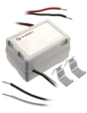
For operation directly from the AC line, and without the need for any additional components, the CUI VLED15 family of modules includes about 24 LED drivers (Figure 4), and offers simplicity of use and installation. The members of this 6.5 to 17 W constant-current family span a wide range of current/voltage pairings, such as 8-12 V/1.25 A, and 24-48 V/350 mA. An additional benefit of this module approach is that the supplies come with full regulatory approval and compliance, and are available for operation directly from 90 to 135 V and 176 to 265 V AC-lines. To help engineers with their designs, CUI also offers a Product Training Module for the VLED15 family on the DigiKey website.

Figure 4: The members of the VLED15 series of LED drivers from CUI Inc. are complete AC/DC supplies that need no additional components and meet all regulatory requirements, and are designed to support moderate-size LED arrays.
Summary
Large numbers of LEDs in a variety of array configurations are increasingly being used for display backlighting, area illumination, and digital signage. While driving a single or even a few LEDs is fairly straightforward, doing so for these larger arrays brings issues of the overall LED interconnection topology, as well as options for powering and even controlling the array. This article has examined some of the issues, options, and trade-offs when configuring a larger array and providing DC power to it via LED drivers.
For more information on the parts discussed here, use the links provided to access product information pages on the DigiKey website.
免责声明:各个作者和/或论坛参与者在本网站发表的观点、看法和意见不代表 DigiKey 的观点、看法和意见,也不代表 DigiKey 官方政策。


