Power Conversion Topology Critical for HB LED Designs
投稿人:Convergence Promotions LLC
2012-07-10
High-brightness LEDs (HB LEDs) encompass a broad category of devices that includes many shades of white and RGB colors. A dizzying number of devices are available, each suited for a particular application. All have the common feature, however, of generating lots of light very efficiently – enough light for environmental illumination in applications such as automotive, room and architectural lighting, street lighting, projection displays, and display backlighting.
More light requires more power, and this brings the thermal sensitivity of LEDs into play as a major engineering consideration. The nature of LEDs means that small changes in voltage result in large changes in current – as well as dramatic changes in brightness.
Controlling HB LEDs requires more design sophistication than applications such as status lights or low-intensity appliance lighting. High-brightness LED control requires a constant current that must be accurately maintained over varying voltage and temperature. In addition to basic design considerations, other issues such as cost, EMI, and energy efficiency are also important. This makes the choice of a power regulator topology one of the first considerations in an HB LED driver design. There are four basic power topologies for achieving control in switch-mode LED drivers: linear regulators, buck convertors, boost converters, and several types of buck-boost converters. These topologies – and when to use them – are the top-level engineering decision for designers and the primary focus of this article.
HB LED basics
HB LEDs have been in use for several years, and their introduction vastly expanded LED applications. The primary factors that create the high-brightness class of LEDs, however, are not the materials or manufacturing of the LEDs themselves but the solution of problems associated with heat failure and diminished performance. The original LED application – indicator lights – used a through-hole wired package design. Because this type of packaging is not very efficient at removing the heat, a standard 5 mm LED might produce as much as three lumens and operate at about 100 mW input power.
Two developments solved the heat problem: adopting surface-mount technology, which allowed the PC board to be used as a heat sink; and, adding a thermal heat slug directly into the bottom of the surface mount package. Because the slug was right under the LED junction, heat could be removed far more effectively. In addition, improved LED manufacturing processes have boosted the efficiency of the LED itself. Improvements continue at a rapid pace. Cree's XLamp XP-G LEDs, for example, deliver up to 140 lumens per watt and have a maximum drive current of 1,500 mA – a far cry from three lumens at 100 mW of status lights.
Driving HB LEDs
HB LEDs require a constant drive current regardless of operating conditions and maintaining this current is particularly problematic when batteries are the energy supply. Automotive applications are challenging because the battery might supply as much as 16 volts or as little as 8 volts depending on its load, operating temperature and age. Computer displays that use HB LEDs as a source of back-lighting have a fairly wide operating range because the supply voltage can vary ±10 percent and still be considered within a normal range. Even electric mains supplies can be problematic given the sensitivity of HB LEDs. The situation can be expected to worsen as distributed energy sources such as solar energy are integrated into the grid in significant numbers.
The forward voltage VF of an HB LED determines its forward current IF. Since VF varies with LED die temperature, the constant-current regulator has to be flexible enough to accommodate expected temperature changes. In addition, LEDs are binned according to color, brightness and forward voltage with VF being allowed to vary the most. This is important because HB LED arrays are typically connected in series to ensure a common IF. The upshot from a design perspective is that in order to guarantee that a true constant current is delivered to each LED in an array, the power topology must be capable of delivering an output voltage equal to the sum of the maximum forward voltages of every device placed in the string.
Application scenarios
Designers have three scenarios to consider before they start their design: situations in which the input voltage (VIN) exceeds the sum of the maximum forward voltages (ΣVF); when VIN is less than ΣVF; and when the range of VIN overlaps ΣVF – in other words, sometimes above and sometimes below it.
When VIN always exceeds ΣVF, two options are available: linear regulators and buck regulators. Linear regulators have the advantages of simplicity, low part count and exceptionally low EMI (electromagnetic interference). They can deliver constant current as long as the VF in the LED string does not exceed their dropout-limited output voltage. They should be considered in designs that do not demand high efficiency. Power dissipation in a linear regulator LED driver is equal to approximately (VIN – n x VF) x IF , where "n" is the number of LEDs in the string. A design in which IF exceeds 300 mA, however, usually requires a heat sink, which adds to the design’s cost and size.
Step-down or buck regulators typically offer a more energy efficient solution in situations when VIN always exceeds ΣVF. The regulator must be adjustable with the adjustment made with two feedback resistors. By replacing one resistor with the LED string and using a current-sensing resistor in place of the other resistor, designers can cause the voltage source to adjust the output voltage until enough current flows through the current sensing resistor to equal the feedback voltage of the IC.
Although the circuit design is more complex and has more EMI switching noise than a linear regulator, buck regulators deliver high efficiency, which in turn eliminates the need for a heat sink. Many buck regulators switch at 1 MHz and above, which makes their external components so small that at currents under one ampere they may actually use less space than a linear regulator.
Step-up – also known as boost – regulators are similar to linear and buck regulators in at least one way: as long as they have a feedback divider network, they can be modified into a constant current source. One important difference, however, is critical to designers. When the power switch is internal to a control IC, there is a fixed current limit to take into account.
In buck regulators, the internal switch passes the same DC current as the LED. In a boost converter, the internal switch passes a higher current that varies with input voltage. Therefore, when using monolithic boost regulator-based LED drivers, designers must avoid exceeding the fixed current limit over the range of input voltage.
In some applications, a current regulator that can both buck and boost is needed. Topologies include the SEPIC, flyback, and VIN referenced buck-boost, which is also known as the floating buck-boost.
In all of these topologies, the power-switch current exceeds the LED current and varies with input voltage. The same attention to maximum switch current must be made over the full range of input voltage, especially if a regulator is implemented with an internal power switch and fixed current limit.
HB LED automotive applications
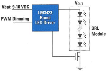
HB LEDs can be used almost anywhere in a car where illumination is needed, but each application typically requires different LEDs and a well chosen power conversion topology. One of the simplest applications is a car’s daytime running lights (DRL). A typical configuration – as shown in Figure 1 – has the circuit driving a single string of 12 one-watt HB LEDs connected in series and getting power from a 12 volt battery.
The first design consideration is whether the sum of the 12 HB LEDs voltages exceeds the sum of the LED forward voltages. Since VF in this class of HB LEDs is always three volts or greater, the sum invariably exceeds the 12 volt input. Some boost converter topology is the best choice. Many power converter ICs are capable of implementing multiple topologies. In this example, National Semiconductor’s LM3423 is a good choice because it is considered a buck/boost driver. Maxim’s MAX16803 can also be used in this application. Maxim offers a MAX16803 evaluation kit for developers interested in pursuing such designs.

Figure 1: Automobile daytime running lights require a boost convertor to drive the HB LEDs (Courtesy of National Semiconductor).
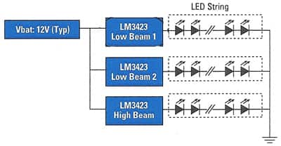
Driving automobile headlamps presents a different scenario because each string (high beam/low beam) can be powered either directly by the 12 volt battery or by a 24 volt automotive bus. Figure 2 shows a typical arrangement in which three controllers are used to drive three strings. Because of the different input voltages, the sum for forward voltages may be either more or less than the power supply so a buck/boost topology is required. As with the previous example, National Semiconductor’s previously mentioned LM3423 can be used – although in this application it is configured in a buck/boost topology. Linear Technology’s LT3755 can also be used in automobile headlamp applications.

Figure 2: Multiple power supplies make automobile headlamps a candidate for buck/boost topologies (Courtesy of National Semiconductor).
LED projector application
Portable projection systems have a few characteristics that make the design of a power converter quite different than white LED strings in headlamps. Projectors require RGB color, which is typically implemented using a 5 mm module containing red, green and blue LEDs. The three LEDs share the same positive (anode) terminal. In this "common anode" connection the module has only four wire connectors. Each LED color is controlled through the cathode. Projectors also consume a lot of power, which makes heat dissipation extremely important for LED-based systems. The common anode connection is helpful here as well because the anodes of multiple LEDs can be tied directly to the ground referenced chassis for maximum heat sink efficacy.
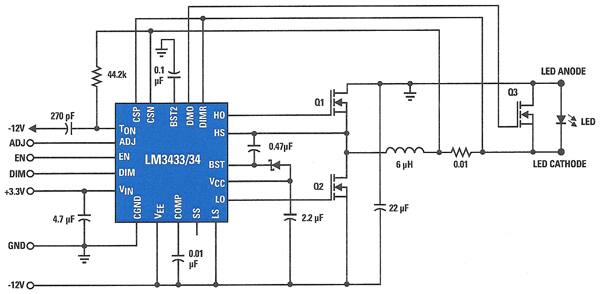
Power controller manufacturers offer solutions compatible with HB LED common-anode modules. Because RGB color components are mixed to obtain the desired color, each LED requires one LM3433 driver to drive it independently. National Semiconductor’s LM3433, for example, uses a negative synchronous buck topology and is targeted at applications where a common anode LED system is used for high current output. A typical application circuit is shown in Figure 3. National Semiconductor offers an LM3433 evaluation board as well as a product training module that explains its PowerWise products and technology.

Figure 3: Portable projectors are an application well suited for common anode HB LED modules driven by a negative synchronous buck topology (Courtesy of National Semiconductor).
Conclusion
The nature of HB LEDs requires a constant current to avoid performance issues and this is not necessarily easy to accomplish in the most elegant design. Choosing the right power topology for an HB LED application is critical for success and each application has its own particular demands. Linear regulators are sometimes used because of their relatively poor efficiency. But their low EMI and low cost suits them for some applications. Buck converters are the best choice when the power supply voltage is less than the sum of LED forward voltages. Buck/boost topologies cover all voltage input possibilities but have lower efficiencies than buck converters. Semiconductor vendors have designed chips that can be customized to achieve multiple topologies, which makes design easier but increases bill of materials costs.

免责声明:各个作者和/或论坛参与者在本网站发表的观点、看法和意见不代表 DigiKey 的观点、看法和意见,也不代表 DigiKey 官方政策。


