KEMET’s New Thermorite® Temperature Sensor with Built-In ON/OFF Reed Switch
投稿人:DigiKey
2020-05-27
Introduction
Temperature sensors are widely used in many applications to control and monitor the temperature of the system and take actions accordingly.
In a majority of the cases, the temperature sensor is an Integrated Circuit (IC) chip or a module that outputs the temperature information via various interfaces to an MCU which, based on this reading, decides what action to take.
This approach has a lot of advantages but requires understanding in electronics, involvement in the design process and time to implement.
If a simple ON/OFF functionality is required, like for example, just to turn on the fan or temporarily turn off the power supply if a system is getting hot and come back to normal operation when it is getting cooler again, mechanical thermostats like those pictured in Figure 1 have been used for many years.
 Figure 1: Images of the mechanical thermostats. (Image source: DigiKey)
These mechanical thermostats are based on bimetallic elements which are two pieces of different metals expanding at different rates as they are heated and are bonded together to form a bimetal disc or strip.
The strip works as a bridge in an electrical circuit connected to the power supply flow. Normally, the strip carries electricity through the circuit. When the strip gets hot, one of the metals expands more than the other so the whole strip bends and breaks (opens) the circuit (Figure 2).
 Figure 2: The principle of bimetallic thermostat. (Image source: Chegg.com)
Some of the mechanical bimetallic thermostat vendors that DigiKey carries include Bourns, Cantherm, Honeywell Sensing, Littelfuse, and Sensata.
In some other cases, thermistors (NTC or PTC) are used (Figure 3). They monitor the temperature by resistance change due to temperature change. But they still need control circuitry and a physical switch to provide ON or OFF functionality.
 Figure 3: Images of the thermistors. (Image source: Electrical4u.com)
KEMET recently introduced thermostat switches based on a patent technology
from Tokin (a vendor acquired by KEMET in 2017). In a nutshell, the technology is based on French physicist Pierre Curie’s discovery that at a certain temperature a permanent magnet will lose its magnetic properties. This temperature is now known as the so-called “Curie Point”. Using some patented techniques, TOKIN has created a material which can control, monitor and adjust this “Curie Point”. This material, known as Thermorite®, combined with a well-known reed switch technology, creates a thermal switch which opens or closes when this very specific and tightly controlled temperature (also known as a “set point” or “trigger temperature”) is reached (Figure 4).
 Figure 4: Basic structure of the Thermorite® temperature switch. (Image source: KEMET)
Thermorite switch advantages vs. mechanical bi-metallic thermostats
The primary advantages of Thermorite switches are:
- High reliability (long product lifetime)
- Excellent environmental resistance to dust, explosion, moisture, and corrosion
- Wide temperature setting range
- High precision (accuracy)
- Fast response time
- Time stability (no ageing)
Table 1 shows the basic comparisons between these two technologies.
|
Table 1: Comparison of KEMET Thermorite switches and bimetallic thermostats.
KEMET thermal sensors basic construction and operation principle
There are two types of KEMET thermal sensors: “Break” type (SPST-NO) and “Make” type (SPST-NC).
Break-type (SPST-NO) Switch
The break type switch consists of a Thermorite cylinder that surrounds the reeds. At both ends of the cylinder are ring-shaped permanent magnets as shown in Figure 5.
 Figure 5: Structure of break-type sensor. (Image source: KEMET)
Below the temperature set point (trigger temperature), the Thermorite acts as a magnetic material and creates a single magnetic field that acts on the opposing permanent magnet poles in the reeds, causing them to be connected, thus turning the switch "ON".
When the temperature set point is exceeded, the Thermorite loses its magnetic property. At this point the single magnetic field becomes two separate fields associated with the permanent magnets at each end of the switch, causing the contacts to separate. This turns the switch "OFF".
Make-type (SPST-NC) Switch
The make-type switch has a similar structure to the break type, except for an additional spacer (gap) inserted in the middle of the Thermorite cylinder to create an action opposite to break-type switch behavior as shown in Figure 6.
 Figure 6: Make-type switch structure. (Image source: KEMET)
Below the temperature set point (trigger temperature), the spacer causes the permanent magnets and Thermorite to create two independent magnetic fields that act in a similar way to those of the break-type sensor in high-temperature mode. The contacts are separated and the switch is turned “OFF”.
When the temperature set point is exceeded, the Thermorite loses its magnetic property. At this point, two independent fields of the permanent magnets act on the ends of the reeds causing the contacts to stick, thus turning the switch “ON”.
In both “break” and “make” types, when the sensor cools down, it comes back to it is normal state ("ON" for break type and “OFF” for “make type). Figure 7 shows this ON/OFF cycle for the “break” type sensor and Figure 8 shows this OFF/ON cycle for the “make” type sensor.
The temperature point of resuming the normal state is called the recovery temperature or reset temperature. The difference between the set point (trigger temperature) and recovery/reset temperature is called the differential temperature.
 Figure 7: ON/OFF cycle for the “break” type sensor. (Image source: KEMET)
 Figure 8: OFF/ON cycle for the “make” type sensor. (Image source: KEMET)
Table 2 summarizes the switch states at temperatures above and below the set point defined by Thermorite composition.
|
Table 2: Summary of switch status at temperatures above and below set point.
KEMET thermal switches product offering
KEMET offers two series: the TRS series and the OHD series. Both series have “break (ON/OFF)” and “make (OFF/ON)” types.
In general, break-type switches are used for heater-control applications, whereas make-type switches are for controlling cooling devices such as fans or refrigerators.
The TRS thermal reed switch series are high-precision sensors for temperature-control applications, offering a standard accuracy of ±2.5°C. There are six product lines, which are available in the following packages (Figure 9):
 Figure 9: Available packages for the TRS series. (Image source: KEMET)
More information on the TRS series can be found in the TRS series datasheet.
The TRS series supports a wide range of operating temperatures from -10°C to +130°C. Some TRS5 devices are certified to UL, CSA and VDE safety specifications. Designers can choose 100 V or 200 V voltage ratings and maximum power ratings from 6 W to 72 W.
The OHD Thermal Guard switches are used where simple overheating protection is required. OHD Thermal Guard switches are accurate to ±5°C and can be used with signals from extremely low power levels of about 0.1 mW up to 6 W. Temperature set points are available in 5°C increments from 30°C to 130°C.
Three package styles are available:
- OHD3 bolt-down package with solder tabs
- OHD1 axial-leaded package for through-hole board mounting
- OHD5R radial-leaded through-hole package that is ideal for use in tight spaces.
Figure 10 shows the available packages for the OHD series.
 Figure 10: Available packages for the OHD series. (Image source: KEMET)
More information on the OHD series can be found in the OHD series datasheet.
Table 3 summarizes the main differences between the TRS and OHD series.

Table 3: The differences between the TRS and OHD series.
The experiments
In a test of these sensors, the two parameters highlighted in Table 4 were focused upon.

Table 4: TRS series temperature characteristics. (Image source: KEMET)
Experiment 1, TRS series
The test equipment:
1. KEMET TRS5 sensors:
- TRS5-60BLR00V (399-18231-ND): 60°C, 264 VAC, break type
- TRS5-100BLR00V (399-18235-ND: 100°C, 264 VAC, break type
 Figure 11: A KEMET TRS5 sensor. (Image source: DigiKey)
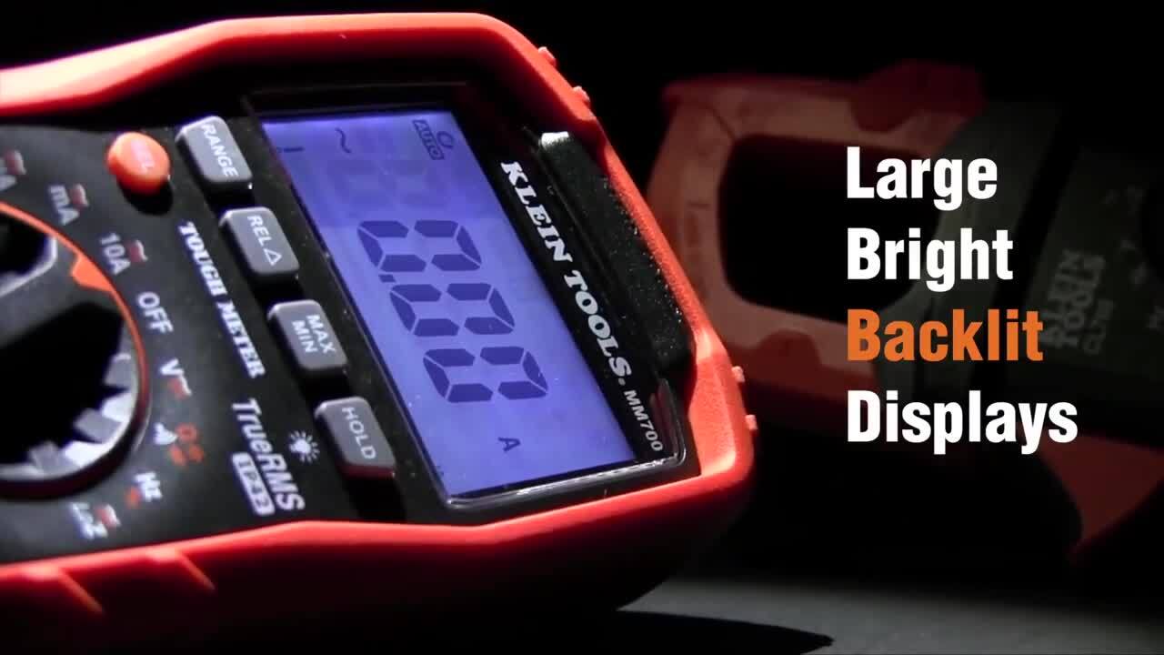
2. Klein Tools Digital Thermometer, ET05 (1742-1249-ND)
 Figure 12: Klein Tools ET05 digital thermometer. (Image source: Klein Tools)
3. 220 V bulb with bulb holder
 Figure 13: 220 V bulb and holder. (Image source: DigiKey)
4. Candle
TRS5 test procedure:
The TRS5-60BLR00V and TRS5-100BLR00V sensors were connected in series between the hot mains wire and the bulb holder wire.
 Figure 14: Bulb and holder connected to power cord. (Image source: DigiKey)
Measuring the sensor temperature using Klein thermometer is rather challenging.
 Figure 15: Klein thermometer and KEMET TRS560BLR00V. (Image source: DigiKey)
To aid in temperature measurement, the sensor and the Klein thermometer probe were wrapped in aluminum foil to create a more or less uniform ambient temperature using a “stove oven” effect. It is not the most efficient method to measure the temperature and the Klein thermometer is not the best or most accurate tool, but for simplicity sake, it still gives good results in understanding the sensor behavior.
 Figure 16: Wrapping the Klein thermometer probe and temperature sensor in foil to create a “stove oven” effect to aid in temperature measurement. (Image source: DigiKey)
The final experiment set up is as in below Figure 17.
 Figure 17: Experiment set-up with TRS5-60BLR00V. (Image source: DigiKey)
Plugging the bulb with the TRS5-60BLR00V or TRS5-100BLR00V sensor in series to the mains turns the bulb on. Then the candle was used to heat the sensor.
As it can be seen in Figures 18 and 19, at 58.6°C for the 60 degree sensor (TRS5-60BLR00V) and at 98.8°C for the 100 degree sensor (TRS5-100BLR00V) the bulb is still on.
 Figures 18 and 19: TRS5-60BLR00V and TRS5-100BLR00V (Image source: DigiKey)
This experiment was repeated several times and the ON/OFF switching occurred very close to the sensors’ switching temperature value: 59-62°C for the 60°C sensor and 99°C to 102°C for the 100°C sensor. So, the switching temperature precision parameter of ±2.5°C is fully met.
Video 1 shows the temperature at which the bulb was turned off – between 59.4 and 60.1°C for the 60 degree sensor (TRS5-60BLR00V).
The next step was to check the “Differential Temperature” parameter which is specified in Table 4 as “10°C Maximum”.
Video 2 shows this experiment. After the sensor reached its switching temperature at 61.4°C for the 60 degree sensor, TRS5-60BLR00V and the bulb turned off. The heating element – the candle – was then moved away from the sensor.
As expected, the temperature kept rising a little and then started to go down. At the temperature of 57.8°C, the bulb turned on again, proving the cycle as shown on Figure 7. From this data, the “Differential Temperature” was determined to be 3.6°C. Additional tests showed similar results – the measured “Differential Temperature” parameter always fell in the range of 3°C to 4°C.
For the 100 degree sensor TRS5-60BLR00V, the tests showed the same results: the “Differential Temperature” was determined to be in the range of 3°C to 4°C.
Experiment 2, OHD sensor
The test equipment:
1. KEMET OHD sensor, OHD1-60M (399-12143-ND): 60°C, 6 W, make type
 Figure 20: KEMET OHD160M. (Image source: DigiKey)
2. Klein Tools Digital Thermometer, ET05 (1742-1249-ND)
 Figure 21: Klein Tools ET05 digital thermometer. (Image source: Klein Tools)
3. LED, 5 mm T-1 3/4 (Broadcom HLMP-3750 (516-1345-ND) was used)
 Figure 22: Broadcom HLMP-3750 LED. (Image source: Broadcom Limited)
4. Twin Industries, breadboard, TW-E41-1020 (438-1046-ND)
 Figure 23: Twin Industries TW-E41-1020 breadboard (Image source: DigiKey)
5. ADI Active Learning Module, ADALM2000 (ADALM2000-ND) as a 5 V Power Supply
 Figure 24: ADI ADALM2000 active learning module. (Image source: Analog Devices Inc.)
6. Candle
OHD1-60M test procedure:
The KEMET OHD 60 degree sensor OHD1-60M was connected in series between the 5 V power supply from the ADALM2000 and the LED (Figure 25).
 Figure 25: Experiment set up with OHD1-60M. (Image source: DigiKey)
Like in the first experiment, the OHD1-60M sensor was wrapped in aluminum foil together with the Klein thermometer probe.
 Figure 26: OHD1-60M sensor and Klein thermometer probe wrapped in foil. (Image source: DigiKey)
As long as the sensor temperature was less than 60°C, the LED was turned off. At the temperature 59.2°C, the LED turned on. Video 3 demonstrates this process.
Repetitive tests showed the same behavior of the sensor. The LED turning on occurs in the temperature range between 59 – 62°C, meeting the specification in the data sheet.
The “Differential Temperature” also was in the range of 3 - 4°C below the “Switching Temperature”.
Conclusion
Implementing KEMET’s TRS and OHD series temperature sensors as ON/OFF temperature switches is very simple, and they provide accurate results without sacrificing precision, stability and reliability. They are available in various voltage ratings, form factors, and a wide range of the switching temperatures. They come in normally open (break type) or normally closed (make type) configurations.
免责声明:各个作者和/或论坛参与者在本网站发表的观点、看法和意见不代表 DigiKey 的观点、看法和意见,也不代表 DigiKey 官方政策。