制造商零件编号 PTS-00196-201
NANO FLIP ATMEGA328P EVAL BRD
PTSolns
Crystals / Oscillators Microcontrollers
This tutorial shows how to verify the frequency of the clock source on a microcontroller development board. The process is similar for a range of boards, but we will use the popular Nano. This is a good exercise to do as it helps the user get a more in-depth understanding of the Nano microcontroller development board.
The Nano uses the ATmega328P, which has an internal clock source running at 8MHz. The chip factory settings relating to the clock (Low Fuse) are such that this internal clock source is used. However, many Nano boards have an external clock source as well, often at either 8MHz or 16MHz. The clock settings (Low Fuse) can be changed such that the external clock source is used. When using this external clock source, it might be of interest to verify that the clock source is working as expected and is indeed of the correct value. That is the goal of this tutorial. We will omit any detailed discussions on fuse settings and instead focus on the methodology on how to verify the clock source.
We will outline two different methods on how to check or verify the clock source. The first method is straightforward, and we will use visual magnification to look at the external clock source. Typically, there is a number corresponding to the frequency engraved on the component. In the second method, we will force the ATmega328P to output the clock signal to digital pin D8 and we will view it with an oscilloscope.
Particularly for Method 2: Oscilloscope, there is some overlap relating to our previous tutorial, Changing Bootloader on a Nano using a Custom Shield. The reader is encouraged to take a look at that tutorial as we discuss how to connect the programmer (Uno) to the target (Nano) and how to burn bootloader onto the target.
For Method 1: Visual Magnification, the reader can simply use their smartphone and take an image (recommended with flash ON) and zoom in on the component. In this tutorial, we use an electronic microscope to read the component's engraving.
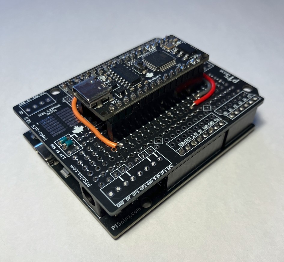
For Method 2: Oscilloscope, the reader obviously needs an oscilloscope. A single-channel scope is fine, as long as it can handle a signal up to 16MHz. Furthermore, for this method, we need another microcontroller development board, such as the Uno or similar. We will use the Uno R3+. Some jumper wires are useful as well, or alternatively, a bootloader Uno shield.
For the Nano, we will use the Nano Flip.
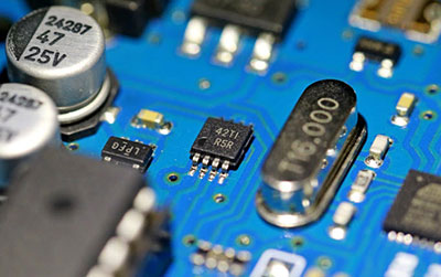
With a phone, a microscope, or similar zoom in on the Nano Flip clock source. This can be found right next to the ATmega328P chip.

From the image, one can see a "16.000" which is referring to the 16MHz of this clock source.
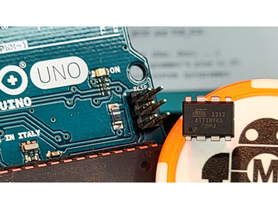
Out of curiosity, we can look at other development boards and their clock sources. The Arduino Uno R3 also uses a 16MHz clock source, although a different type than the Nano Flip.

Finally, we can also look at a TOP SECRET development board that is not yet released ;) and see that this board uses an 8MHz clock source.

However, sometimes a visual inspection is not sufficient to be sure. Particularly with the ATmega328P, which has an internal 8MHz clock source (enabled by factory settings), and the external clock source has a "16" written on it. The user wants to make sure that the external source is used. To do that, we move on to Method 2.
In this method, we first need to adjust the clock settings (Low Fuse) of the ATmega328P. One of the settings (disabled by default) outputs the clock signal to digital pin D8. Another setting tells the chip to use the external clock source and not the default internal one. Both of these settings are part of a larger group of settings in the Low Fuse options.
NOTE: We will not touch any of the other fuses, and the user is encouraged to be careful when changing these, as this could "brick" the Nano.
We refer the reader to a very useful and practical online fuse calculator. In particular, we need to adjust the Low Fuse of the ATmega328P to include the two above-mentioned changes. The default Low Fuse setting is 0x62, which we need to change to 0x9E. To do this, change the Low Fuse settings as follows:

The first setting is enabled, the second setting is disabled, while the third drop-down setting is set to the external crystal for frequencies 8MHz and above. These settings result in a Low Fuse of 0x9E.

The Low Fuse can easily be changed using the Arduino IDE software and the command prompt. First, open the latest Arduino IDE, connect the Uno R3+ (or any other version of the Uno you want/have), and upload the "ArduinoISP" example sketch. After uploading we need to connect the Uno R3+ to the Nano Flip via the SPI signals. It is very straightforward (also explained in our tutorial Changing Bootloader on a Nano using a Custom Shield). Make the following connections using jumper wires.
5V -> 5V
GND -> GND
D13 -> D13
D12 -> D12
D11 -> D11
D10 -> RST
Alternatively, the user can use a bootloader shield, which makes the above connections.
This will allow us to perform the next step, which is to use Command Prompt to tell the Uno R3+ to change the Nano Flip Low Fuse setting, using avrdude.
Open the Command Prompt and navigate (cd) to the folder bin folder of the avrdude. As an example, this could be:
cd "C:\Users\user\AppData\Local\Arduino15\packages\arduino\tools\avrdude\6.3.0-arduino17\bin"
Next, we need to refer to the avrdude.conf file to make the Low Fuse changed. On the computer we are using we need to explicitly state the location. It is a matter of finding it in the correct folder and getting the path. As an example, this could be:
"C:\Users\user\AppData\Local\Arduino15\packages\arduino\tools\avrdude\6.3.0-arduino17\etc\avrdude.conf"
We also need to know which port the Uno R3+ is using. One can easily see this from the Arduino IDE software in the Board and Port settings. In our case, this is Port 6 (COM6).
Finally, we type the following in the Command Prompt, making sure that A) the path is correct and B) the port is correct.
avrdude -C "C:\Users\user\AppData\Local\Arduino15\packages\arduino\tools\avrdude\6.3.0-arduino17\etc\avrdude.conf" -c arduino -p m328p -P COM6 -b 19200 -U lfuse:w:0x9e:m
With the above done, you should see something along the lines of "avrdude done. Thank you". This means we have changed the clock source to the external one and prepared the chip to output this signal on D8. The printout should also state the fuse settings, and the user can cross check all is well. Now the only thing left to do is connect the oscilloscope to it and read the frequency. As can be seen in the image below, the external clock frequency of the Nano Flip is exactly at 16MHz, meaning all is as expected.

In this tutorial, we outlined two methods on how to verify the external clock is what it should be. The user is encouraged to play around with this and try other Low Fuse settings .... just be warned to change the other Fuses carefully, as some of them can "brick" the Nano. Playing around with these things gives the user more confidence not just in the product itself (it is what it claims to be), but also in their own skills and knowledge.
The reader is reminded of our documentation repository, docs.PTSolns.com, which has all the datasheets and supporting materials not just for the Uno R3+ and the Nano Flip, but also all of the PTSolns product line.