制造商零件编号 PTS-00153-211
PROTOTYPING SHIELD FOR ARDUINO K
PTSolns
License: Attribution Microcontrollers Programmers Arduino
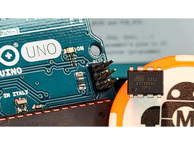
This tutorial demonstrates how to switch between the old and new bootloader on a Nano. The Uno is used to burn the bootloader to the Nano, and a Proto-Shield is used to connect the Uno to the Nano during the burning process. This is a great introductory project for beginners who want to learn about microcontrollers and how to use a shield for prototyping projects. Before starting, you will need to install Arduino IDE and the CH340 driver on your computer (if not already done). The CH340 is the integrated circuit used to transfer information between a computer and the Nano Flip microcontroller (ATmega328P).
A detailed explanation of how to install the CH340 driver (and to check if the computer already has it installed) can be found in Section 6.1 of the Nano Flip datasheet. Alternatively, you can click here to view an in-depth and excellent tutorial on CH340 driver installation done by SparkFun Electronics, as well as links to download the driver for your operating system.
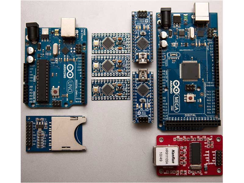
To work through this tutorial, we will need the following:
Nano Flip (Datasheet), but any equivalent Nano development board will work.
Uno R3+ (Datasheet), but any equivalent Uno development board will work.
Proto-Shield (Datasheet)
USB-C cable (data transfer capable)
2pcs 1x15 pin 2.54mm female header
1pcs 1x6 pin 2.54mm male header
2pcs 1x8 pin 2.54mm male header
1pc 1x10 pin 2.54mm male header
Some jumper wires
Soldering equipment
The following sections give a step-by-step description of the process, including photos and diagrams to assist the reader every step of the way.
Note that for this tutorial we are using a Mac computer, with Arduino IDE version 1.8.19. Newer versions of IDE or using a PC environment will have similar steps as outlined here, but they may alter slightly. Most of this tutorial should carry over other platforms.
Before we can burn the bootloader, connections need to be made between the Uno R3+ and the Nano Flip. Table 1 summarizes the connections to be made by soldering wires to the shield. It is recommended to solder the wires to the shield before soldering the 15 pin female headers that the Nano Flip will plug into. Figure 1 and Figure 2 show the Fritzing diagram of the shield with the connections outlined in Table 1. The location of the headers that the Nano Flip will plug into is also shown. These are the two darkened rows with green squares that stretch horizontally across the middle of the diagram. Note the two small red and orange wires that are circled, these wires are to be soldered on the underside of the shield after the headers are soldered in place. To make the shield connections that will link the Uno R3+ to the Nano Flip we will:
Solder the longer wires in place as shown in Figure 1 and Figure 2, and outlined in Table 1.
Solder the headers that the Nano Flip will plug into. Do not solder the Nano Flip directly to the shield.
Solder the two small orange and green wires indicated by the red circles in Figure 1 and Figure 2 on the underside of the shield.
[Table 1: Pin connections between the Uno R3+ and Nano Flip.]
[Figure 1: Fritzing Diagram with 15 pin male-to-female Nano Flip headers. Note the two circled wires that are to be connected on the underside of the shield, after the headers are soldered in place.]
[Figure 2: Fritzing Diagram with Nano Flip placed in headers. Do not solder the Nano Flip directly to the shield.]
[Figure 3: A photo of the assembled shield connecting the Uno R3+ and Nano Flip.]
[Figure 4: A photo of the assembled shield connecting the Uno R3+ and Nano Flip.]
Now that the connecting wires and Nano Flip headers are soldered in place, the shield can be mounted on the Uno R3+. Begin by inserting the male headers into the Uno R3+ and placing the shield on top. If this has been done correctly, all the pin holes on the very top and very bottom of Figure 1 and Figure 2 will have a header going through them and it should easily rest in place. Once this is done, the Uno R3+ headers can be soldered to the shield. Figure 3 and Figure 4 show the completed assembly. Congratulations! The hard part is over. We can now move on to burning the bootloader.
To begin, open up a blank sketch in Arduino IDE and connect the Uno R3+ to your computer using the USB-C cable (data transfer capable). Next, select the board type as Arduino Uno in the Tools tab as in Figure 5. The USB port that the Uno R3+ is plugged into should also be selected at this time, as in Figure 6. Figure 7 demonstrates the next step, which is to open the File tab, go to Examples, and then click on ArduinoISP to load the sketch. Once the ArduinoISP sketch is uploaded, go to the Tools tab and change the board type to Arduino Nano as shown in Figure 9. Once the Nano board has been selected, we can choose between the old and new bootloader (ATmega328P) when selecting the processor, as seen in Figure 10. In this tutorial, we will begin with the old bootloader, test it, then switch to the new bootloader and test that as well. The programmer used to burn the bootloader needs to be changed to Arduino as ISP, in the Tools tab as demonstrated in Figure 11. The final step is demonstrated in Figure 12. In the Tools tab, select Burn Bootloader. In the ArduinoISP sketch, a message will appear that says “Done burning bootloader” to let us know that the burning has successfully been completed.
[Figure 5: In the Tools tab, select the board type as Arduino Uno.]
[Figure 6: In the Tools tab, select the correct USB port that the Uno is plugged into.]
[Figure 7: In the File tab under Examples, load the ArduinoISP sketch.]
[Figure 8: Upload the ArduinoISP sketch to the Uno R3+.]
[Figure 9: In the Tools tab, change the board type from Arduino Uno to Arduino Nano.]
[Figure 10: In the Tools tab, select between the new and old bootloader (ATmega328P) that you would like to burn to the Nano Flip. For this tutorial we will start with the old bootloader.]
[Figure 11: In the Tools tab, change the programmer to Arduino as ISP.]
[Figure 12: In the Tools tab, click on Burn Bootloader.]
It is always a good idea to test the Nano Flip with a simple example sketch after burning the bootloader. To do this, start by unplugging the USB-C cable from the Uno R3+ and remove the Nano Flip from the headers connecting it to the Uno R3+. Plug the USB-C cable into the Nano Flip and open a new sketch in Arduino IDE. Under the tools tab, make sure that the selected board is the Arduino Nano, and the processor is selected to be the old bootloader. The blink example sketch is a simple way to test the Nano Flip and ensure that it is working correctly. In the File tab, go to Examples and select the Basics subfolder. Click on Blink to load the blink sketch. Upload the blink sketch to the Nano Flip as depicted in Figure 13, this will result in the LED on the Nano Flip to begin blinking. The default code tells the Nano Flip to turn the LED on for 1000 ms, then turn it off for 1000 ms, and repeat indefinitely. Try changing the amount of time from 1000 ms to 100 ms as shown in Figure 14. This is done by changing the value of “delay(1000)” to “delay(100)” in the code. Upload the sketch, and the LED starts blinking at a higher frequency.
Now that we know that the Nano Flip is working correctly with the old bootloader, let’s try switching to the new bootloader and see what happens. Under the Tools tab, change the processor from the old bootloader to the new bootloader (ATmega328P) as shown in Figure 15. Now try uploading the blink sketch to the Nano Flip as before. This will result in an error message as seen in Figure 18. Since we have burned the old bootloader, no sketch will be able to upload to the Nano Flip when we simply change the processor to the new bootloader in the Tools tab. In order to upload sketches using the new bootloader, we need to repeat the burning process described in Section 3.1.
[Figure 13: Upload the blink sketch to the Nano Flip.]
[Figure 14: Alter the code to make the LED blink faster. In this example, the timing is changed from 1000 ms to 100 ms. This is done by changing the value of “delay(1000)” to “delay(100)” in the code.]
[Figure 15: Let’s see what happens when we try to new bootloader. In the Tools tab, change the processor from the old bootloader to the new bootloader (ATmega328P).]
[Figure 16: When simply switching the processor from the old bootloader to the new bootloader, an error message appears, and the blink sketch is not able to be uploaded to the Nano Flip.]
To burn the new bootloader, begin by disconnecting the USB-C cable from the Nano Flip. Plug that Nano Flip back into the headers connecting it to the Uno R3+, then plug the USB-C cable into the Uno R3+. Under the File tab, load the ArduinoISP example as outlined in Section 3.1. Under the Tools tab, select the board to be Arduino Uno and upload the sketch. Once the sketch has been successfully uploaded, go to the Tools tab and change the board type to Arduino Nano. Make sure the processor is selected to be the new bootloader (ATmega328P) and the programmer is chosen to be “Arduino as ISP” as in Figure 17. Go to the Tools tab and click on Burn Bootloader. We have now successfully switched from the old bootloader to the new bootloader. As before, we will test the Nano Flip to make sure everything is working properly.
[Figure 17: Upload the ArduinoISP sketch to the Uno R3+. Select the board to be Arduino Nano, the processor to be the new bootloader (ATmega328P), and the programmer to be “Arduino as ISP”. Go to the Tools tab and click on Burn Bootloader.]
[Figure 18: After burning the new bootloader as described in section 3.3, the blink sketch can be successfully uploaded and used with the processor selected as ATmega328P.]
As in Section 3.2, we begin by removing the Nano Flip from the headers and connecting it to the Uno R3+. Unplug the USB-C cable from the Uno R3+ and plug it into the Nano Flip. Go to the Tools tab and make sure the board is chosen to be the Arduino Nano; the processor is the new bootloader (ATmega328P). Then, open and upload the blink sketch. As seen in Figure 18, the sketch is successfully uploaded, and the LED on the Nano Flip is blinking. Recall that we encountered an error message in Section 3.2 when the old bootloader had been burned to the Nano Flip, and we simply tried changing the processor to the new bootloader in the Tools tab. Likewise, now that the new bootloader has been burned, switching the processor to the old bootloader without another burning process will result in an error message when uploading the blink example, as shown in Figure 19.
[Figure 19: The new bootloader has been burned to the Nano Flip. If the processor is simply changed back to the old bootloader in the Tools tab without going through another burning process, an error message will appear when trying to upload the blink sketch.]
This tutorial demonstrated how to switch between the old and new bootloader on a PTSolns Nano Flip. This is done by using a PTSolns Uno R3+ to burn the bootloader to the Nano Flip. A PTSolns Proto-Shield was used to make the required connections between the Uno R3+ and the Nano Flip. To begin, the old bootloader was burned to the Nano Flip. Once the old bootloader had been successfully burned, the Nano Flip was tested by uploading the blink example. Then, the processor was changed to the new bootloader under the Tools tab. This resulted in an error message and the blink example was unable to be loaded onto the Nano Flip. To fix this, the burning process was repeated, but this time burning the new bootloader instead of the old bootloader. After the burning process was completed, the blink example was able to be successfully uploaded to the Nano Flip. As before, if the processor is switched back to the old bootloader without first going through the burning process, the blink example will fail, and an error message will appear.
NOTE: All PTSolns products including the ones used in this tutorial have a detailed datasheet and a plethora of supporting material. All of which is available on our Documentation Repository: docs.PTSolns.com
Datasheets & supporting material on PTSolns Documentation Repository: https://docs.ptsolns.com