制造商零件编号 5325
STEMMA QT QT PY ESP32-S2 WIFI
Adafruit Industries LLC
License: See Original Project 3D Printing LED Strips Solder / Desoldering QT Py
Courtesy of Adafruit
Guide by Ruiz Brothers and 1 other contributor
Overview
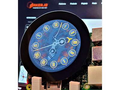
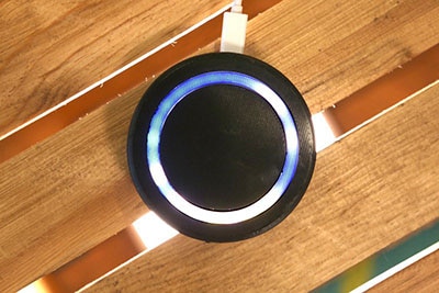
Build an internet-connected Moon Phase clock displaying the current moon cycle on a 3D printed topographical relief of the lunar surface!
Powered by CircuitPython, this clock runs on a QT Py ESP32-S2 with a diffused, high density NeoPixel LED strip.
The NeoPixel strip cycles to show the new moon, waxing crescent, first quarter, waxing gibbous, full moon, waning gibbous, third quarter, and waning crescent.
This project uses the FarmSense API to get the phase of the moon and Adafruit IO to get the Unix timestamp. A request is made every 6 hours (tracked with ticks) to Adafruit IO and the API.
This project is inspired by the Moon Lamp project, originally posted by Martin Kozak.
Parts
Adafruit NeoPixel Silicone Bead LED Strip - 180 LEDs per Meter
5V 1A (1000mA) USB port power supply - UL Listed
To have the moon semi-transparent, the following white PLA filament was used. The black PLA is generic.
1 x White PLA Filament
Circuit Diagram
The diagram below provides a general visual reference for wiring of the components once you get to the Assembly page. This diagram was created using the software package Fritzing.
Adafruit Library for Fritzing
Adafruit uses the Adafruit's Fritzing parts library to create circuit diagrams for projects. You can download the library or just grab individual parts. Get the library and parts from GitHub - Adafruit Fritzing Parts.
Wired Connections
The LED strip connects to the QTPy via a JST SM cable.
Cut the LED strip to be 98 pixels (55.3cm) long. Solder the JST cables such that:
A3 on QT Py connects to LED strip DIN
5V on QT Py connects to LED strip +5V
GND on QT Py connects to LED strip GND
The strip is mounted clockwise and starts at the 6 o'clock position.
Install CircuitPython
CircuitPython is a derivative of MicroPython designed to simplify experimentation and education on low-cost microcontrollers. It makes it easier than ever to get prototyping by requiring no upfront desktop software downloads. Simply copy and edit files on the CIRCUITPY drive to iterate.
CircuitPython Quickstart
Follow this step-by-step to quickly get CircuitPython running on your board.
Download the latest version of CircuitPython for this board via circuitpython.org
Click the link above to download the latest CircuitPython UF2 file.
Save it wherever is convenient for you.
The board above has a chip antenna, not the u.Fl connector, but the process is the same.
Plug your board into your computer, using a known-good data-sync cable, directly, or via an adapter if needed.
Click the reset button once (highlighted in red above), and then click it again when you see the RGB status LED(s) (highlighted in green above) turn purple (approximately half a second later). Sometimes it helps to think of it as a "slow double-click" of the reset button.
If you do not see the LED turning purple, you will need to reinstall the UF2 bootloader. See the Factory Reset page in this guide for details.
On some very old versions of the UF2 bootloader, the status LED turns red instead of purple.
For this board, tap reset and wait for the LED to turn purple, and as soon as it turns purple, tap reset again. The second tap needs to happen while the LED is still purple.
Once successful, you will see the RGB status LED(s) turn green (highlighted in green above). If you see red, try another port, or if you're using an adapter or hub, try without the hub, or different adapter or hub.
If double-clicking doesn't work the first time, try again. Sometimes it can take a few tries to get the rhythm right!
A lot of people end up using charge-only USB cables and it is very frustrating! Make sure you have a USB cable you know is good for data sync.
If after several tries, and verifying your USB cable is data-ready, you still cannot get to the bootloader, it is possible that the bootloader is missing or damaged. Check out the Factory Reset page for details on resolving this issue.
You will see a new disk drive appear called QTPYS2BOOT.
Drag the adafruit_circuitpython_etc.uf2 file to QTPYS2BOOT.
The BOOT drive will disappear, and a new disk drive called CIRCUITPY will appear.
That's it!
Create Your settings.toml File
CircuitPython works with WiFi-capable boards to enable you to make projects that have network connectivity. This means working with various passwords and API keys. As of CircuitPython 8, there is support for a settings.toml file. This is a file that is stored on your CIRCUITPY drive, which contains all of your secret network information, such as your SSID, SSID password and any API keys for IoT services. It is designed to separate your sensitive information from your code.py file so you are able to share your code without sharing your credentials.
CircuitPython previously used a secrets.py file for this purpose. The settings.toml file is quite similar.
Your settings.toml file should be stored in the main directory of your CIRCUITPY drive. It should not be in a folder.
CircuitPython settings.toml File
This section will provide a couple of examples of what your settings.toml file should look like, specifically for CircuitPython WiFi projects in general.
The most minimal settings.toml file must contain your WiFi SSID and password, as that is the minimum required to connect to WiFi. Copy this example, paste it into your settings.toml, and update:
your_wifi_ssid
your_wifi_password
CIRCUITPY_WIFI_SSID = "your_wifi_ssid"
CIRCUITPY_WIFI_PASSWORD = "your_wifi_password"
Many CircuitPython network-connected projects on the Adafruit Learn System involve using Adafruit IO. For these projects, you must also include your Adafruit IO username and key. Copy the following example, paste it into your settings.toml file, and update:
your_wifi_ssid
your_wifi_password
your_aio_username
your_aio_key
CIRCUITPY_WIFI_SSID = "your_wifi_ssid"
CIRCUITPY_WIFI_PASSWORD = "your_wifi_password"
ADAFRUIT_AIO_USERNAME = "your_aio_username"
ADAFRUIT_AIO_KEY = "your_aio_key"
Some projects use different variable names for the entries in the settings.toml file. For example, a project might use ADAFRUIT_AIO_ID in the place of ADAFRUIT_AIO_USERNAME. If you run into connectivity issues, one of the first things to check is that the names in the settings.toml file match the names in the code.
Not every project uses the same variable name for each entry in the settings.toml file! Always verify it matches the code.
settings.toml File Tips
Here is an example settings.toml file.
# Comments are supported
CIRCUITPY_WIFI_SSID = "guest wifi"
CIRCUITPY_WIFI_PASSWORD = "guessable"
CIRCUITPY_WEB_API_PORT = 80
CIRCUITPY_WEB_API_PASSWORD = "passw0rd"
test_variable = "this is a test"
thumbs_up = "\U0001f44d"
In a settings.toml file, it's important to keep these factors in mind:
Strings are wrapped in double quotes; ex: "your-string-here"
Integers are not quoted and may be written in decimal with optional sign (+1, -1, 1000) or hexadecimal (0xabcd).
Use \u escapes for weird characters, \x and \ooo escapes are not available in .toml files
Unicode emoji, and non-ASCII characters, stand for themselves as long as you're careful to save in "UTF-8 without BOM" format
When your settings.toml file is ready, you can save it in your text editor with the .toml extension.
Accessing Your settings.toml Information in code.py
In your code.py file, you'll need to import the os library to access the settings.toml file. Your settings are accessed with the os.getenv() function. You'll pass your settings entry to the function to import it into the code.py file.
import os

print(os.getenv("test_variable"))
In the upcoming CircuitPython WiFi examples, you'll see how the settings.toml file is used for connecting to your SSID and accessing your API keys.
Code
Once you've finished setting up your QT Py ESP32-S2 with CircuitPython, you can access the code and necessary libraries by downloading the Project Bundle.
To do this, click on the Download Project Bundle button in the window below. It will download to your computer as a zipped folder.
# SPDX-FileCopyrightText: 2025 Liz Clark for Adafruit Industries
# SPDX-License-Identifier: MIT

import os
import time
import ssl
import board
import wifi
import socketpool
import microcontroller
import neopixel
import adafruit_requests
from adafruit_ticks import ticks_ms, ticks_add, ticks_diff

# FarmSense API for moon phase
# https://www.farmsense.net/api/astro-widgets/
url = "https://api.farmsense.net/v1/moonphases/?d="
# Adafruit IO time server for UNIX time, no API key needed
time_url = "https://io.adafruit.com/api/v2/time/seconds"
# connect to wifi
try:
    wifi.radio.connect(os.getenv('CIRCUITPY_WIFI_SSID'), os.getenv('CIRCUITPY_WIFI_PASSWORD'))
except TypeError:
    print("Could not find WiFi info. Check your settings.toml file!")
    raise
pool = socketpool.SocketPool(wifi.radio)
requests = adafruit_requests.Session(pool, ssl.create_default_context())

# neopixels, 49 total
OFF = (0, 0, 0)
ON = (255, 255, 255)
pixel_pin = board.A3
num_pixels = 49
pixels = neopixel.NeoPixel(pixel_pin, num_pixels, brightness=0.1, auto_write=False)
pixels.fill(0)

# phases of the moon
NEW_MOON = 0
WAXING_CRESCENT = 1
FIRST_QUARTER = 2
WAXING_GIBBOUS = 3
FULL_MOON = 4
WANING_GIBBOUS = 5
THIRD_QUARTER = 6
WANING_CRESCENT = 7
# strings that match return from API
phase_names = ["New Moon", "Waxing Crescent", "First Quarter", "Waxing Gibbous",
          "Full Moon", "Waning Gibbous", "Third Quarter", "Waning Crescent"]

# functions for each moon phase to light up based on neopixel orientation
def set_new_moon():
    pixels.fill(OFF)
    pixels.show()

def set_waxing_crescent():
    pixels.fill(OFF)
    for i in range(31, 44):
        pixels[i] = ON
    pixels.show()

def set_first_quarter():
    pixels.fill(OFF)
    for i in range(24, 49):
        pixels[i] = ON
    pixels.show()

def set_waxing_gibbous():
    pixels.fill(OFF)
    for i in range(0, 4):
        pixels[i] = ON
    for i in range(18, 49):
        pixels[i] = ON
    pixels.show()

def set_full_moon():
    pixels.fill(ON)
    pixels.show()

def set_waning_gibbous():
    pixels.fill(OFF)
    for i in range(0, 30):
        pixels[i] = ON
    for i in range(44, 49):
        pixels[i] = ON
    pixels.show()

def set_third_quarter():
    pixels.fill(OFF)
    for i in range(0, 24):
        pixels[i] = ON
    pixels.show()

def set_waning_crescent():
    pixels.fill(OFF)
    for i in range(5, 18):
        pixels[i] = ON
    pixels.show()

# match functions with phases
phase_functions = {
    NEW_MOON: set_new_moon,
    WAXING_CRESCENT: set_waxing_crescent,
    FIRST_QUARTER: set_first_quarter,
    WAXING_GIBBOUS: set_waxing_gibbous,
    FULL_MOON: set_full_moon,
    WANING_GIBBOUS: set_waning_gibbous,
    THIRD_QUARTER: set_third_quarter,
    WANING_CRESCENT: set_waning_crescent
}

# test function, runs through all 8 in order
def demo_all_phases(delay=1):
    for phase in range(8):
        print(f"Setting phase: {phase_names[phase]}")
        phase_functions[phase]()
        time.sleep(delay)
demo_all_phases()

# takes response from API, matches to function, runs function
def set_moon_phase(phase):
    phase_lower = phase.lower()
    for i, name in enumerate(phase_names):
        if phase_lower == name.lower():
            phase_functions[i]()
            print(f"Moon phase set to: {name}")

# time keeping, fetches API every 6 hours
timer_clock = ticks_ms()
timer = (6 * 3600) * 1000
first_run = True

while True:
    try:
        if first_run or ticks_diff(ticks_ms(), timer_clock) >= timer:
			# get unix time
            unix_time = requests.get(time_url)
			# update farmsense request with UNIX time
            url = f"https://api.farmsense.net/v1/moonphases/?d={unix_time.text}"
			# get the JSON response
            response = requests.get(url)
            json_response = response.json()
			# isolate phase info
            print("-" * 40)
            print(json_response[0]['Phase'])
            print("-" * 40)
			# run function to update neopixels with current phase
            set_moon_phase(json_response[0]['Phase'])
            response.close()
            time.sleep(1)
            first_run = False
			# reset clock
            timer_clock = ticks_add(timer_clock, timer)
    # pylint: disable=broad-except
    except Exception as e:
        print("Error:\n", str(e))
        print("Resetting microcontroller in 10 seconds")
        time.sleep(10)
        microcontroller.reset()
Upload the Code and Libraries to the QT Py
After downloading the Project Bundle, plug your QT Py into the computer's USB port with a known good USB data+power cable. You should see a new flash drive appear in the computer's File Explorer or Finder (depending on your operating system) called CIRCUITPY. Unzip the folder and copy the following items to the QT Py's CIRCUITPY drive.
lib folder
code.py
Your QT Py ESP32-S2 CIRCUITPY drive should look like this after copying the lib folder and the code.py file.
Add Your settings.toml File
As of CircuitPython 8.0.0, there is support for Environment Variables. Environment variables are stored in a settings.toml file. Similar to secrets.py, the settings.toml file separates your sensitive information from your main code.py file. Add your settings.toml file as described in the Create Your settings.toml File page earlier in this guide. You'll need to include your CIRCUITPY_WIFI_SSID and CIRCUITPY_WIFI_PASSWORD. Adafruit IO credentials and other data are not needed for this project.
CIRCUITPY_WIFI_SSID = "your-ssid-here"
CIRCUITPY_WIFI_PASSWORD = "your-ssid-password-here"
How the Code Works
The moon phase information is fetched from the FarmSense API. It is a free API that supplies agricultural data such as day lengths, frost dates and, most importantly for this project, moon phases. For the moon phase API, you supply the request with the current Unix timestamp. You'll use the Adafruit IO time API to fetch the Unix timestamp. You do not need to include your Adafruit IO key to use this API.
# FarmSense API for moon phase
# https://www.farmsense.net/api/astro-widgets/
url = "https://api.farmsense.net/v1/moonphases/?d="
# Adafruit IO time server for UNIX time, no API key needed
time_url = "https://io.adafruit.com/api/v2/time/seconds"
# connect to wifi
try:
    wifi.radio.connect(os.getenv('CIRCUITPY_WIFI_SSID'), os.getenv('CIRCUITPY_WIFI_PASSWORD'))
except TypeError:
    print("Could not find WiFi info. Check your settings.toml file!")
    raise
pool = socketpool.SocketPool(wifi.radio)
requests = adafruit_requests.Session(pool, ssl.create_default_context())
NeoPixels
The NeoPixels are setup on pin A3. Two colors are defined: OFF (all pixels off) and ON (white). To start, the NeoPixels are turned off to reset any pixels.
# neopixels, 49 total
OFF = (0, 0, 0)
ON = (255, 255, 255)
pixel_pin = board.A3
num_pixels = 49
pixels = neopixel.NeoPixel(pixel_pin, num_pixels, brightness=0.1, auto_write=False)
pixels.fill(0)
Phases of the Moon
The phases of the moon are returned as strings from the API. The list phase_names is created to store these strings. Variables for the phases are also created.
# phases of the moon
NEW_MOON = 0
WAXING_CRESCENT = 1
FIRST_QUARTER = 2
WAXING_GIBBOUS = 3
FULL_MOON = 4
WANING_GIBBOUS = 5
THIRD_QUARTER = 6
WANING_CRESCENT = 7
# strings that match return from API
phase_names = ["New Moon", "Waxing Crescent", "First Quarter", "Waxing Gibbous",
          "Full Moon", "Waning Gibbous", "Third Quarter", "Waning Crescent"]
Each phase has a function that turns the necessary NeoPixels on or off to display the phase. For example, set_new_moon() turns all of the pixels off. set_third_quarter() sets half of the pixels on.
def set_new_moon():
    pixels.fill(OFF)
    pixels.show()

...

def set_third_quarter():
    pixels.fill(OFF)
    for i in range(0, 24):
        pixels[i] = ON
    pixels.show()
These functions are matched to the phase and phase index with the phase_functions dictionary.
# match functions with phases
phase_functions = {
    NEW_MOON: set_new_moon,
    WAXING_CRESCENT: set_waxing_crescent,
    FIRST_QUARTER: set_first_quarter,
    WAXING_GIBBOUS: set_waxing_gibbous,
    FULL_MOON: set_full_moon,
    WANING_GIBBOUS: set_waning_gibbous,
    THIRD_QUARTER: set_third_quarter,
    WANING_CRESCENT: set_waning_crescent
}
The set_moon_phase() function takes the current phase returned from the API and runs the matching NeoPixel function to set the NeoPixels.
# takes response from API, matches to function, runs function
def set_moon_phase(phase):
    phase_lower = phase.lower()
    for i, name in enumerate(phase_names):
        if phase_lower == name.lower():
            phase_functions[i]()
            print(f"Moon phase set to: {name}")
The Loop
In the loop, ticks is used to keep time. Every 6 hours, the Unix timestamp is fetched from the Adafruit IO time API. The timestamp is packed into the FarmSense API request as an f-string. The FarmSense API returns a JSON file. The 'Phase' index contains the current phase of the moon as a string. This string is passed to the set_moon_phase() function to update the NeoPixels.
if first_run or ticks_diff(ticks_ms(), timer_clock) >= timer:
			# get unix time
            unix_time = requests.get(time_url)
			# update farmsense request with UNIX time
            url = f"https://api.farmsense.net/v1/moonphases/?d={unix_time.text}"
			# get the JSON response
            response = requests.get(url)
            json_response = response.json()
			# isolate phase info
            print("-" * 40)
            print(json_response[0]['Phase'])
            print("-" * 40)
			# run function to update neopixels with current phase
            set_moon_phase(json_response[0]['Phase'])
            response.close()
            time.sleep(1)
            first_run = False
			# reset clock
timer_clock = ticks_add(timer_clock, timer)3D Printing
3D Printed Parts
STL files for 3D printing will need to be oriented for print using either FDM or SLS machines.
Parts were printed with PLA filament. The black is generic. The white used is specified in Parts on the Overview page.
Original design source files may be downloaded using the links below.
Slice with settings for PLA material.
The parts were sliced using BambuStudio using the slice settings below.
PLA filament 220c extruder
0.28-layer height
10% gyroid infill
200mm/s print speed
60c heated bed
Supports: Slim Tree / Z top distance .28
Assembly
Solder QTPy
Position the JST SM wires away from the edges of the QTPy board when soldering to help avoid the corners of the press-fit holder.
QTPy holder screws
Prepare the printed holder by attach two M2.5x6mm screws.
Mount QTPy
Insert the QTPy with the STEMMA QT port first, then gently press on the USB connector to attach to the holder.
Attach the case
Fasten the holder to the screw holes inside the case. Position the USB port to the cutout on the side on the case.
Measure LED strip
Use a tape measure to cut 55.3cm or 98 pixels. Start measuring after the socket connector and wires.
Cut the strip along the center of the pad between the LEDs.
Connect strip
Align the socket and plug wires to connect the LED strip.
Press-fit LED strip
Align the start of the strip to the cut out along the channel inside the case. Press-fit a small portion of the strip into the channel.
Insert the moon print at an angle to fit inside the case. Press each side until it sits below the LED channel.
Fit strip end
Gently press fit the rest of the strip in the channel, working your way from the start of the strip to the end.
Place cover
The LED cover helps to hide the LED strip and is fitted over the case.