制造商零件编号 5420
MEMENTO DIY CAMERA MAIN BOARD
Adafruit Industries LLC
License: See Original Project 3D Printing Proximity STEMMA
Courtesy of Adafruit
Guide by Ruiz Brothers and 1 other contributor
Overview
WiFi Bird Feeder Camera
This project captures images of birds that you can view on an Adafruit IO feed or dashboard.
We designed and 3D printed a bird feeder to house the Adafruit MEMENTO, a large battery, and a PIR sensor. It’s got a tray for holding birdseed and a perch so birds can visit and have a meal.
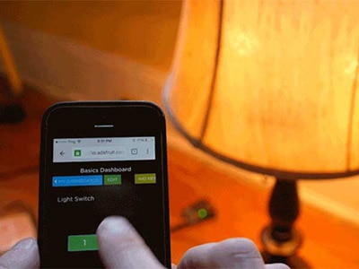
Adafruit IO Camera Feed
When the PIR sensor detects motion, the MEMENTO takes a photo and sends a JPEG to Adafruit IO.
On the Adafruit IO website, you can view the image within seconds of it being captured. Using Adafruit IO’s Actions feature, you can receive email notifications whenever a new photo is uploaded.
Capture Wildlife
The bird feeder isn’t exclusive to just birds - squirrels and chipmunks are fans too and they seem to be a bit more photogenic!
Our build features a large battery that has about eight hours of run time and can be recharged over the MEMENTO USB port.
Parts
Adafruit IO+ Subscription Pass – One Year
1 x 2200mAh Battery
The following parts are useful, but optional for completion of this project.
1 x Heat Shrink Pack
Hardware
The following hardware is necessary for the case assembly.
2x M2.5 x 6mm long machine screws
2x M3 x 10mm long FF standoffs
10x M3 x 6mm long machine screws
4x M3 x 10mm long machine screws
6x M3 hex nuts
Text editor powered by tinymce.
Wiring
Connect PIR Sensor to JST PH 3-Pin Plug
In the wiring diagram below, the PIR sensor is connected to one of the MEMENTO's JST PH 3-Pin sockets. However, it's not as simple as the diagram makes it out to be. The PIR sensor comes with a 30cm cable ending in a socket.
There are a few options for connecting this cable to the MEMENTO's JST-PH socket:
Alligator Clips
This option requires no soldering. Simply follow the wiring diagram and connect the JST PH cable's alligator clips to the wires from the PIR sensor's cable.
DIY Wiring Harness
This option requires soldering. However, it is permanent and elegant compared to the alligator clips.
You'll need the following parts for this step:
Using wire cutters, cut a JST PH 2mm 3-pin Plug-Plug cable in half. Then, add heat shrink tubing over the cable.
Solder each wire of the JST PH cable to the corresponding wire on the PIR sensor's harness.
Then, slide the heat shrink tubing over the soldering joint and apply heat.
After soldering and applying heat shrink to all three cables, your PIR sensor is ready to be plugged into the MEMENTO.
Wiring Diagram
After connecting the PIR sensor to a JST cable, connect the cable to the MEMENTO.
The wiring for this project is as follows:
PIR Sensor VCC to Memento A0 VIN
PIR Sensor GND to Memento A0 GND
PIR Sensor Output to Memento A0 Signal
Text editor powered by tinymce.
CAD Files
3D Printed Parts
STL files for 3D printing are oriented to print "as-is" on FDM style machines. Parts are designed to 3D print without any support material using PLA filament. Original design source may be downloaded using the links below.
Build Volume
The parts require a 3D printer with a minimum build volume.
182mm (X) x 128mm (Y) x 92mm (Z)
CAD Assembly
The PIR sensor and battery is secured to brackets using machine screws. The brackets are secured to the MEMENTO using machine screws. The MEMENTO is secured to the front half of the enclosure using machine screws. The back half of the enclosure is secured to the house plate using screws, hex nuts and standoffs. The roof and feeding tray are secured to the house plate using machine screws and hex nuts. The front and back enclosure parts snap fit together.
Design Source Files
The project assembly was designed in Fusion 360. This can be downloaded in different formats like STEP, STL and more.
Electronic components like Adafruit's boards, displays, connectors and more can be downloaded from the Adafruit CAD parts GitHub Repo.
Text editor powered by tinymce.
Get Started with Adafruit IO
Adafruit IO is integrated with your adafruit.com account so you don't need to create yet another online account! You need an Adafruit account to use Adafruit IO because we want to make sure the data you upload is available to only you (unless you decide to publish your data).
I have an Adafruit.com Account already
If you already have an Adafruit account, then you already have access to Adafruit IO. It doesn't matter how you signed up, your account will make all three available.
To access Adafruit IO, simply visit https://io.adafruit.com to start streaming, logging, and interacting with your data.
Create an Adafruit Account (for Adafruit IO)
An Adafruit account makes Adafruit content and services available to you in one place. Your account provides access to the Adafruit shop, the Adafruit Learning System, and Adafruit IO. This means only one account, one username, and one password are necessary to engage with the content and services that Adafruit offers.
If you do not have an Adafruit account, signing up for a new Adafruit account only takes a couple of steps.
Begin by visiting https://accounts.adafruit.com.
Click the Sign Up button under the "Need An Adafruit Account?" title, below the Sign In section.
This will take you to the Sign Up page.
Fill in the requested information and click the Create Account button.
This takes you to your Adafruit Account home page. From here, you can access all the features of your account.
You can also access the Adafruit content and services right from this page. Along the top of the page, you'll see a series of links beginning with "Shop". To access any of these, simply click the link.
For example, to begin working with Adafruit IO, click the IO link to the right of the rest of the links. This is the same for the other links as well.
That's all there is to creating a new Adafruit account and navigating to Adafruit IO.
Text editor powered by tinymce.
Create Adafruit IO Feed
These steps are REQUIRED to use the birdfeeder camera. Skipping it will result in errors!
Feeds are the core of the Adafruit IO system. A feed holds data and meta-data that you have sent to Adafruit IO.
Data is the information you want Adafruit IO to store. For example, image data from the MEMENTO's camera.
Meta-data includes settings for the data such as privacy settings and data retention options.
Before using the IoT Birdfeeder, a new Adafruit IO Feed must be created to store the MEMENTO camera's image. Then, the feed's history must be disabled to allow larger data points to be sent to Adafruit IO, such as a large amount of data to represent an image.
To create a feed, navigate to your Adafruit IO Feeds page. Then, click New Feed.
Name the feed birdfeeder and click Create.
The feeds list now lists a birdfeeder feed. Click this feed.
Disable Feed History
On the camera feed's sidebar, click Feed History.
Set History to OFF and click Save. This will change the feed's data storage from 1KB to 100KB, large enough to store image data.
Text editor powered by tinymce.
Create Your settings.toml File
CircuitPython works with WiFi-capable boards to enable you to make projects that have network connectivity. This means working with various passwords and API keys. As of CircuitPython 8, there is support for a settings.toml file. This is a file that is stored on your CIRCUITPY drive, which contains all of your secret network information, such as your SSID, SSID password and any API keys for IoT services. It is designed to separate your sensitive information from your code.py file so you are able to share your code without sharing your credentials.
CircuitPython previously used a secrets.py file for this purpose. The settings.toml file is quite similar.
Your settings.toml file should be stored in the main directory of your CIRCUITPY drive. It should not be in a folder.
CircuitPython settings.toml File
This section will provide a couple of examples of what your settings.toml file should look like, specifically for CircuitPython WiFi projects in general.
The most minimal settings.toml file must contain your WiFi SSID and password, as that is the minimum required to connect to WiFi. Copy this example, paste it into your settings.toml, and update:
your_wifi_ssid
your_wifi_password
CIRCUITPY_WIFI_SSID = "your_wifi_ssid"
CIRCUITPY_WIFI_PASSWORD = "your_wifi_password"
Many CircuitPython network-connected projects on the Adafruit Learn System involve using Adafruit IO. For these projects, you must also include your Adafruit IO username and key. Copy the following example, paste it into your settings.toml file, and update:
your_wifi_ssid
your_wifi_password
your_aio_username
your_aio_key
CIRCUITPY_WIFI_SSID = "your_wifi_ssid"
CIRCUITPY_WIFI_PASSWORD = "your_wifi_password"
ADAFRUIT_AIO_USERNAME = "your_aio_username"
ADAFRUIT_AIO_KEY = "your_aio_key"
Some projects use different variable names for the entries in the settings.toml file. For example, a project might use ADAFRUIT_AIO_ID in the place of ADAFRUIT_AIO_USERNAME. If you run into connectivity issues, one of the first things to check is that the names in the settings.toml file match the names in the code.
Not every project uses the same variable name for each entry in the settings.toml file! Always verify it matches the code.
settings.toml File Tips
Here is an example settings.toml file.
# Comments are supported
CIRCUITPY_WIFI_SSID = "guest wifi"
CIRCUITPY_WIFI_PASSWORD = "guessable"
CIRCUITPY_WEB_API_PORT = 80
CIRCUITPY_WEB_API_PASSWORD = "passw0rd"
test_variable = "this is a test"
thumbs_up = "\U0001f44d"
In a settings.toml file, it's important to keep these factors in mind:
Strings are wrapped in double quotes; ex: "your-string-here"
Integers are not quoted and may be written in decimal with optional sign (+1, -1, 1000) or hexadecimal (0xabcd).
Floats, octal (0o567) and binary (0b11011) are not supported.
Use \u escapes for weird characters, \x and \ooo escapes are not available in .toml files
Example: \U0001f44d for 👍 (thumbs up emoji) and \u20ac for € (EUR sign)
Unicode emoji, and non-ASCII characters, stand for themselves as long as you're careful to save in "UTF-8 without BOM" format
When your settings.toml file is ready, you can save it in your text editor with the .toml extension.
Accessing Your settings.toml Information in code.py
In your code.py file, you'll need to import the os library to access the settings.toml file. Your settings are accessed with the os.getenv() function. You'll pass your settings entry to the function to import it into the code.py file.
import os

print(os.getenv("test_variable"))
In the upcoming CircuitPython WiFi examples, you'll see how the settings.toml file is used for connecting to your SSID and accessing your API keys.
Text editor powered by tinymce.
Code
Once you've finished setting up your MEMENTO camera with CircuitPython, you can access the code and necessary libraries by downloading the Project Bundle.
To do this, click on the Download Project Bundle button in the window below. It will download to your computer as a zipped folder.
# SPDX-FileCopyrightText: 2023 Brent Rubell for Adafruit Industries
# SPDX-License-Identifier: MIT
#
# An open-source IoT birdfeeder camera with Adafruit MEMENTO

import os
import ssl
import binascii
import board
import digitalio
import socketpool
import wifi
import adafruit_pycamera
import adafruit_requests
from adafruit_io.adafruit_io import IO_HTTP, AdafruitIO_RequestError

print("MEMENTO Birdfeeder Camera")

### WiFi ###
# Add settings.toml to your filesystem CIRCUITPY_WIFI_SSID and CIRCUITPY_WIFI_PASSWORD keys
# with your WiFi credentials. DO NOT share that file or commit it into Git or other
# source control.

# Set your Adafruit IO Username, Key and Port in settings.toml
# (visit io.adafruit.com if you need to create an account,
# or if you need your Adafruit IO key.)
aio_username = os.getenv("ADAFRUIT_AIO_USERNAME")
aio_key = os.getenv("ADAFRUIT_AIO_KEY")

#print(f"Connecting to {os.getenv('CIRCUITPY_WIFI_SSID')}")
wifi.radio.connect(os.getenv("CIRCUITPY_WIFI_SSID"), os.getenv("CIRCUITPY_WIFI_PASSWORD"))
#print(f"Connected to {os.getenv('CIRCUITPY_WIFI_SSID')}!")

pool = socketpool.SocketPool(wifi.radio)
requests = adafruit_requests.Session(pool, ssl.create_default_context())

# Initialize an Adafruit IO HTTP API object
io = IO_HTTP(aio_username, aio_key, requests)

try:
    # Get the 'birdfeeder' feed from Adafruit IO
    feed_camera = io.get_feed("birdfeeder")
except AdafruitIO_RequestError:
    # If no 'birdfeeder' feed exists, create one
    feed_camera = io.create_new_feed("birdfeeder")

# initialize camera
pycam = adafruit_pycamera.PyCamera()
# turn off the display backlight
pycam.display.brightness = 0.0
# set photo resolution
pycam.resolution = 3
# set focus to estimated bird location
pycam.autofocus_vcm_step = 145

# initialize PIR sensor
pir = digitalio.DigitalInOut(board.A0)
pir.direction = digitalio.Direction.INPUT

def send_jpeg_to_io():
    # before we send the image to IO, it needs to be encoded into base64
    encoded_data = binascii.b2a_base64(jpeg).strip()
    # then, send the encoded_data to Adafruit IO camera feed
    print("Sending image to IO...")
    io.send_data(feed_camera["key"], encoded_data)
    print("Sent image to IO!")

print("Waiting for movement...")
old_pir_value = pir.value
while True:
    pir_value = pir.value
    # if we detect movement, take a photo
    if pir_value:
        if not old_pir_value:
            print("Movement detected, taking picture!")
            # take a picture and save it into a jpeg bytes object
            jpeg = pycam.capture_into_jpeg()
            # if the camera successfully captured a jpeg, send it to IO
            if jpeg is not None:
                send_jpeg_to_io()
            else:
                print("ERROR: JPEG capture failed!")
    else:
        if old_pir_value:
            print("Movement ended")
        # update old_pir_value
    old_pir_value = pir_value
After downloading the Project Bundle, plug your MEMENTO into the computer's USB port with a known good USB data+power cable. You should see a new flash drive appear in the computer's File Explorer or Finder (depending on your operating system) called CIRCUITPY. Unzip the folder and copy the following items to the MEMENTO's CIRCUITPY drive.
lib folder
code.py
Your MEMENTO CIRCUITPY drive should look like this after copying the lib folder and the code.py file.
Code Walkthrough
The following code snippet connects the MEMENTO camera to a WiFi network.
### WiFi ###
# Add settings.toml to your filesystem CIRCUITPY_WIFI_SSID and CIRCUITPY_WIFI_PASSWORD keys
# with your WiFi credentials. DO NOT share that file or commit it into Git or other
# source control.

# Set your Adafruit IO Username, Key and Port in settings.toml
# (visit io.adafruit.com if you need to create an account,
# or if you need your Adafruit IO key.)
aio_username = os.getenv("ADAFRUIT_AIO_USERNAME")
aio_key = os.getenv("ADAFRUIT_AIO_KEY")

print(f"Connecting to {os.getenv('CIRCUITPY_WIFI_SSID')}")
wifi.radio.connect(
    os.getenv("CIRCUITPY_WIFI_SSID"), os.getenv("CIRCUITPY_WIFI_PASSWORD")
)
print(f"Connected to {os.getenv('CIRCUITPY_WIFI_SSID')}!")
The io object is created to interface with the Adafruit IO HTTP API.
pool = socketpool.SocketPool(wifi.radio)
requests = adafruit_requests.Session(pool, ssl.create_default_context())

# Initialize an Adafruit IO HTTP API object
io = IO_HTTP(os.getenv("ADAFRUIT_AIO_USERNAME"), os.getenv("ADAFRUIT_AIO_KEY"), requests)
We'll attempt to get the birdfeeder feed from Adafruit IO. If it does not exist on the account, the Adafruit IO CircuitPython library will automatically create one.
# Manage Adafruit IO Feed
try:
    # Get the 'birdfeeder' feed from Adafruit IO
    feed_camera = io.get_feed("birdfeeder")
except AdafruitIO_RequestError:
    # If no 'birdfeeder' feed exists, create one
    feed_camera = io.create_new_feed("birdfeeder")
The camera is initialized and its display backlight is disabled.
# initialize camera
pycam = adafruit_pycamera.PyCamera()
# turn off the display backlight
pycam.display.brightness = 0.0
The PIR sensor is initialized as a digital input on the MEMENTO's A0 port.
# initialize PIR sensor
pir = digitalio.DigitalInOut(board.A0)
pir.direction = digitalio.Direction.INPUT
The loop reads the value of the PIR sensor. If the value of the PIR sensor has changed, movement is detected, and the MEMENTO takes a photo. The photo is saved into a JPEG (bytes) object.
print("Waiting for movement...")
old_pir_value = pir.value
while True:
  pir_value = pir.value
  # if we detect movement, take a photo
  if pir_value:
    if not old_pir_value:
      print("Movement detected, taking picture!")
      # force camera autofocus
      pycam.autofocus()
      # take a picture and save it into a jpeg bytes object
      jpeg = pycam.capture_into_jpeg()
If the camera successfully captures a photo, the jpeg object will be full of bytes. The code checks if the jpeg capture was successful and then calls a function to send the jpeg data to Adafruit IO.
If the image is not captured, an error will be printed to the REPL.
# if the camera successfully captured a jpeg, send it to IO
      if jpeg is not None:
        send_jpeg_to_io()
      else:
        print("ERROR: JPEG capture failed!")
The following function, send_jpeg_to_io(), is called by the snippet above. In this function, the jpeg data gets encoded from bytes into a base 64 object to reduce its size. Then, the encoded data is sent to the Adafruit IO feed we specified earlier.
def send_jpeg_to_io():
  """ Sends a JPEG image to Adafruit IO. """
  # before we send the image to IO, it needs to be encoded into base64
  encoded_data = binascii.b2a_base64(jpeg).strip()
  # then, send the encoded_data to Adafruit IO camera feed
  print("Sending image to IO...")
  io.send_data(feed_camera["key"], encoded_data)
  print("Sent image to IO!")
Finally, if the new value detected by the PIR sensor was the previous value, we'll print to the REPL that movement has stopped being detected. The old_pir_value is updated each loop iteration.
else:
    if old_pir_value:
      print("Movement ended")
# update old_pir_value
old_pir_value = pir_value
Text editor powered by tinymce.
Assembly
Wired PIR Sensor
The PIR sensor cable is shorted to be 3.5 inches (8.9mm) long to better fit inside the 3D printed enclosure. (See Wiring page in this guide for more info.)
PIR Sensor Bracket
Use the following hardware to secure the PIR sensor to the 3D printed bracket.
2x M2.5 x 6mm long machine screws
Secure PIR Sensor
Place the PIR sensor PCB over the 3D printed bracket using the photo to reference the correct placement and orientation.
Install and fasten the machine screws to secure the PIR sensor to the 3D printed bracket.
Secure PIR Sensor Bracket
Use two M3 x 6mm long screws to secure to the 3D printed PIR sensor bracket to the back side of the MEMENTO.
The 3D printed bracket for the PIR sensor is placed below the two lower standoffs on the MEMENTO PCB.
Install and fasten the M3 machine screws to secure the PIR sensor bracket to the MEMENTO.
Connect PIR Sensor
Plug the 3-pin JST connector from the PIR sensor to the JST connector on the side of the MEMENTO labeled A0.
Take a moment to ensure the bracket is tightly secured and the PIR sensor is connected to the correct port on the MEMENTO.
Battery Bracket
Use the following hardware to secure the battery bracket to the MEMENTO.
2x M3 x 6mm long machine screws
Secure Battery Bracket
Place the 3D printed battery bracket over the two upper standoffs on the back side of the MEMENTO.
Use the M3 machine screws to secure the 3D printed battery bracket to the MEMENTO.
Plug in the cable from the 2200mAh battery to the battery port on the front side of the MEMENTO.
Install Battery
Press or slide the 2200mAh battery into the clip on the 3D printed battery bracket.
Take a moment to ensure the battery and bracket are installed correctly.
Front Case
Use the following hardware to secure the MEMENTO to the front half of the 3D printed enclosure.
4x M3 x 6mm long machine screws
Fit the MEMENTO into the 3D printed enclosure with the front side facing down.
Secure Memento
Install and fasten the M3 machine screws to secure the MEMENTO to the front half of the 3D printed enclosure.
The lens and PIR sensor should fit through the corresponding cutouts.
Ensure the print-in-place slide switch is positioned to actuate the built-in ON/OFF slide switch onboard the MEMENTO.
House and Tray
Use the following hardware to secure the 3D printed house plate to the feeder tray.
2x M3 x 10mm long machine screws
2x M3 hex nuts
Secure Tray to House
Slide the feeder tray into the bottom of the house plate and line up the mounting holes.
Insert and fasten the M3 screws through the side of the 3D printed house plate.
Use the M3 hex nuts to secure the house plate to the feeder tray.
House & Roof
Use the following hardware to secure the 3D printed house plate to the 3D printed roof.
2x M3 x 10mm long screws
2x M3 hex nuts
Secure Roof to House Plate
Place the 3D printed roof over the top of the 3D printed house plate and line up the mounting holes.
Insert and fasten the M3 screws through the side of the 3D printed roof.
Use the M3 hex nuts to secure the 3D printed roof to the house plate.
Back Case
Use the following hardware to secure the back half of the 3D printed enclosure.
6x M3 x 6mm long machine screws
2x M3 hex nuts
2x M3 x 10mm long FF standoffs
Install Standoffs
Secure the two M3 standoffs using two M3 machine screws to the two upper mounting holes on the 3D printed house plate.
Secure Back Case
Place the back half of the 3D printed enclosure over the standoffs with the side indentation oriented towards the right side.
Install and fasten two M3 screws to secure the back half of the enclosure to the standoffs on the 3D printed house plate.
Secured Case
Install and fasten two M3 screws to the remaining mounting holes.
Use two M3 hex nuts to secure the back half of the 3D printed enclosure to the 3D printed house plate.
Take a moment to ensure the parts are correctly oriented.
Snap Fit Case Closed
Orient the front half of the 3D printed enclosure to match the back half.
Line up the edges and firmly press the two halves to snap fit them together.
Congratulations on building your IoT Bird Feeder!
Text editor powered by tinymce.
Usage
Using Outdoors
The 3D printed enclosure is not fully weatherproof and should only be used outdoors during the day under dry conditions.
Add your preferred bird food to the 3D printed tray.
Birds can be very cautious when eating. Allow a few days for birds to be conformable with your location before expecting them to feed.
Viewing the latest photo on Adafruit IO
The MEMENTO takes a photo when a bird (or any other object) is detected by the feeder's motion sensor. This photo is then uploaded to Adafruit IO.
To view the image from the camera, navigate to your Adafruit IO Feeds page and click on the birdhouse feed.
The image captured by the camera should appear on the feed as a data-point and an image preview will be visible.
If the PIR sensor is not detecting motion in front of it, or if it's too sensitive, follow the instructions below to adjust the sensor's settings.
Adjusting PIR Sensor Sensitivity
The PIR sensor sold by Adafruit has two potentiometers on the back, with one labeled SENSITIVITY. You can adjust the sensitivity if your PIR is too sensitive or not sensitive enough.
Turning the potentiometer clockwise makes it more sensitive and turning it counter-clockwise makes it less sensitive.
Adjusting PIR Sensor Pulse Time and Timeout Length
There are two 'timeouts' associated with the PIR sensor. One is the "Tx" timeout: how long the LED is lit after it detects movement - this is easy to adjust on Adafruit PIR sensors because there's a potentiometer labeled TIME.
For information about the math to adjust pulse time and timeout length, visit this Adafruit Learning System Guide >>>
PIR Motion Sensor
By Lady Ada
Text editor powered by tinymce.