制造商零件编号 857
BLACK PS/2,USB KEYBOARD
Adafruit Industries LLC
License: Attribution 3D Printer Raspberry Pi SBC
The term “cyberdeck” comes from the 1984 novel “Neuromancer” by William Gibson. In the 1980s, the idea of a laptop was in its infancy; monitors, keyboards, and batteries were all large and cumbersome. So, in Gibson’s seminal cyberpunk novel, characters carried around clunky portable desktops known as “cybercecks.” These decks allowed the characters to access the “matrix” (the sci-fi precursor to the Internet).
Hacakday announced a cyberdeck-building contest for August and September of 2022. Jayy and I thought it would be fun to build our own (even if we couldn’t win). We wanted to start simple and chronicle the journey. Hopefully, our notes will help inspire you to build your own ‘deck!
A video demonstrating how to connect all of the electronics can be found here:
Hardware
You might have a vision of what you want to build and what aesthetic you want your custom cyberdeck to have. I’ll focus on the guts of the build–making it a usable computer.
Most custom cyberdecks revolve around a Raspberry Pi, as they are easy to work with and have lots of available accessories. While you can use a different single-board computer (or even a microcontroller), we stick with a Raspberry Pi Zero W. It’s small enough for the mini-build we’re making, and it’s low-power to keep the battery drain down.
Here are the basic parts you will need. Note that you’ll also need some wire, a 1k resistor (if you want your switch to light up, as mine does in the video), and a 3D printer to make your case.
Once you have an idea of how you will lay out your parts, I recommend buying cables that are close to the exact length you need. Otherwise, you’ll end up having to loop and bundle them inside your case (taking up more room than necessary). For our mini-laptop type build, here is what we used:
Connections
You will need to connect the components together as follows:
Layout
One of the most important steps is to lay out your large components to fit in your desired space and to avoid cable bundling as much as possible. You will also want to think about what ports should be available on the side of your case. Do you just want a power switch? Do you need access to USB ports? Do you want to do some hardware hacking and need access to the Raspberry Pi GPIO pin?
We went with a folding LCD to keep it easy, but feel free to get creative with your layout. Here are some fun designs to give you some ideas:
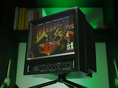
You can also look at or reuse vintage computing equipment and toys for inspiration, like this deck based on the VTech PreComputer 1000.
For this build, Jayy and I wanted to have all of the electronics (except for the LCD) reside underneath the keyboard. The LCD should fold on top of the keyboard, much like a regular laptop.
I found the best way to lay out the parts was to draw (or tape) the footprint of my desired case. Then, organize the parts in a way that makes sense, trying to maximize the available ports and minimize cable runs/crossings. From there, measure and mark out the components, noting where mounting holes and ports should go.
In case you want to replicate our layout, here is a close-up of that diagram. Note that I did not report the distance from the left wall to the nearby components. I left this up to Jayy to decide exactly how far away the components should be from the wall.
Power Section
The simplest option for power would be to expose your Pi’s power connector and simply plug into an A/C adapter or portable battery charger (the big external batteries you probably have to keep your smartphone charged throughout the day). However, I wanted to keep everything internal as much as possible.
To accomplish this, I soldered a LiPo pack onto the Tiny UPS 3.0 board. I removed the power jumper and soldered in a main switch so that I could turn the deck on and off. Finally, I provided a 5V and ground connection from the Tiny UPS board to the USB hub so that it could be self-powered.
A few things to note (i.e. lessons learned):
The Tiny UPS 3.0 has a leakage current of 5-10 mA, even when everything is off. This means your 3000 mAh battery will slowly discharge over a few weeks. To remedy this, you may want to use a DPDT switch to disconnect the battery as well, but it means your battery won’t charge when the deck is off.
The Tiny UPS quickly cycles power if you unplug the USB power cable, likely due to the strain on the battery. Make sure you unplug the A/C adapter first before removing the USB plug. Alternatively, you could try 18650 LiPo cells to see if they are able to provide more continuous current than the LiPo pouch that I used (and thus prevent the power from cycling on disconnect).
Antenna Hack
Because the Pi Zero will be inside of a case, I decided to add an external antenna to hopefully boost my WiFi and Bluetooth reception. To do this, you will need to solder a u.FL connector to the Pi Zero and reroute the antenna signal on the board. This fantastic guide walks you through how to do that.
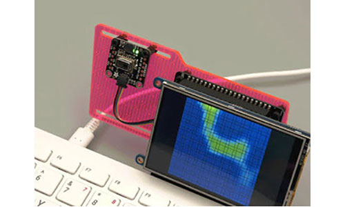
Smoke Test
We want to make sure the system works. Connect everything as shown above before mounting it in your case.
This is a good time to configure your operating system if necessary. I won’t go into the details of configuring the OS in this tutorial. I’m using basic Raspberry Pi OS on the Raspberry Pi Zero W. There is a great guide on confiugring Raspberry Pi OS here. Feel free to load whatever OS you want (assuming it will run). I hear that real console cowboys use Kali Linux.
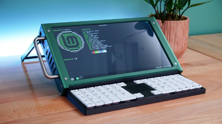
Case Design
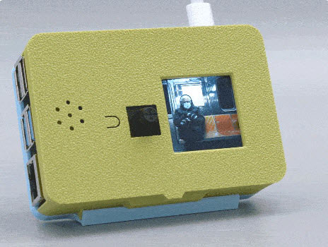
Design your case however you see fit! Jayy designed the case for this joint project using the dimensions I provided. Here is how our first iteration came out:
Recommended Reading
Check out the Hackaday Cyberdeck contest and other projects to get some fun inspiration!