制造商零件编号 SS443R
MAGNETIC SWITCH UNIPOLAR TO92-3
Honeywell Sensing and Productivity Solutions
Today we’re taking a look inside the Belkin Auto-tracking Stand Pro. We’ll try it out, take it apart, and analyze the design and manufacturing of the circuitry inside.
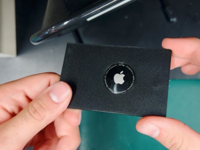
So, here’s the Belkin Auto-Tracking Stand Pro. It’s got a simple but solid design. Snap your phone into the Magsafe connector, and the stand automatically rotates to track you. It’s a cool piece of tech, and the first product to use Apple’s new DockKit accessories standard. Previously, products like this would be limited to capturing with their own apps, but now the DockKit system allows the stand to seamlessly integrate with the native camera app while capturing content or during video calls.
It has a battery inside, which makes it portable. It has a tripod mount on the bottom. It moves super smoothly and quietly, so I’m curious what’s going on inside.
Before taking it apart, I sent the device off to Lumafield to be CT scanned.

The first step of taking it apart is to remove the sticker on the bottom, which hides some screws. But this thing is a super awkward shape, so to keep it flipped upside down, I placed it over the edge of my table.
Removing the bottommost piece of plastic reveals the first of two circuit boards, connected to the rest of the wiring through this free-rotating slip ring, which allows it to spin 360 without tangling any wires. After removing a few more screws, the main body of the base came free, revealing a large, heavy bearing to support that smooth rotational motion. After unplugging the wire connected to the NFC antenna, I was able to remove the top body plastic.
Then I cut the zip ties holding the battery in place and unplugged all the wires from the nearby connectors. Next, I unscrewed the first of two stepper motors. It was connected to the base through a set of gears, controlling the rotation. At this point, I was able to remove the first circuit board, the slip ring, and the large bearing.
Continuing on, there were a few bolts with antislip nuts holding onto the second stepper motor, and a few screws connected to the upright piece. Inside this long neck is a belt that was driven by the second stepper, and some more wires.
.gif?la=en&ts=11a4312a-28c6-4922-820f-0192cf8f5fd9 "Belkin Stand Pro Teardown What Makes Auto-Tracking Work?")
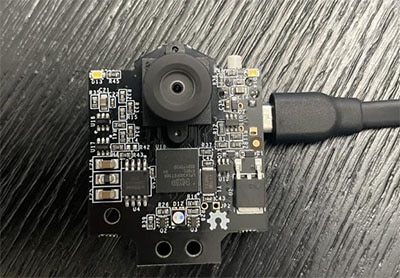
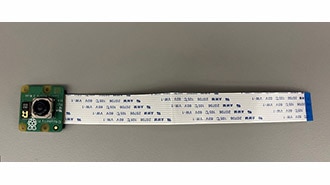
Inside the pivot point is another bearing, a small circuit board, and wires leading to the magnetic charger. Taking a look at all the parts, you could reuse a lot of these for other projects.

My channel’s favorite electrical engineer, David Cranor, joined me to analyze the design and manufacturing of these boards. Watch the video to hear more about what we found!

Here are all the components we could identify:
You can explore the CT scan of the device on Lumafield.