Use the Right Switching Regulator for Efficiency, Low Rail Noise, and a Fast Transient Response
投稿人:DigiKey 北美编辑
2025-06-26
The quality of the DC rail is a critical factor in maintaining system performance in applications such as wireless connectivity, which rely on analog circuits with low signal levels, and in digital designs with low supply rail voltages. In addition to conversion efficiency, output accuracy, stability, and line and load regulation, the DC rail quality is also characterized by factors such as its inherent noise and transient response to dynamic load shifts.
However, multiple generations of advances in Analog Devices’ robust Silent Switcher series have resulted in technology that, when applied appropriately, can provide the requisite low-noise DC output and ultra-fast transient response.
This article focuses on these easy-to-use, high-performance DC/DC switching regulators, the problems they address, and the benefits they bring. It uses application examples from Analog Devices to show how to maximize their performance.
The Silent Switcher family
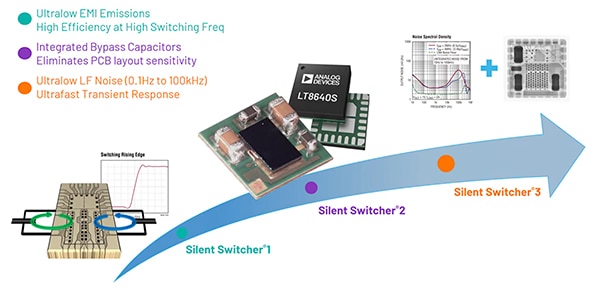
The Silent Switcher family of DC/DC switching regulators from Analog Devices is now in its third generation. The first generation, Silent Switcher 1, focused on reducing high-frequency noise associated with switching regulators. It simultaneously provided three key benefits: low electromagnetic interference (EMI), high efficiency, and high switching frequency (for smaller related components).
Subsequently, Analog Devices introduced the Silent Switcher 2, which retained the features of its predecessor and added integrated precision capacitors, a more compact form factor, and the elimination of sensitivity to printed circuit board (pc board) layout.
The third generation, Silent Switcher 3, builds on the unique capabilities of the first two. It adds benefits that include fast transient response and ultra-low noise in the low-frequency band (Figure 1).
Figure 1: Each successive generation of the Silent Switcher DC/DC regulator has retained and then added to the features and functions of its predecessor. (Image source: Analog Devices)
Simple Switcher noise solutions
To achieve the low noise of the first two generations, designers examined the multiple noise sources and explored innovative ways to work around, minimize, or even cancel them. This required a multifaceted approach. For example, the primary noise source in a switched-mode power supply is the switching of currents, rather than steady-state current flow. In the topology of a conventional switching regulator, there is a current-flow path called a hot loop. The hot loop is the primary source of high-frequency noise that is emitted into the air, causing EMI. The first generation of Silent Switcher DC/DC regulators innovatively split the hot loop into two symmetrically shaped current loops. This creates two magnetic fields of opposite polarities such that the radiated noise cancels itself out to a great extent.
The Silent Switcher 2 generation minimizes critical hot loops by integrating input capacitors directly into the IC package.
The architecture supports fast switching edges for high efficiency at high switching frequencies while achieving good EMI performance. Internal ceramic capacitors on the DC input voltage (VIN) help keep the fast AC current loops small for further improvement. The Silent Switcher architecture also uses proprietary design and packaging techniques that maximize efficiency at very high frequencies, enabling it to pass CISPR 25 Class 5 peak EMI limits.
In addition, active voltage positioning (AVP) is used, a technique where the output voltage is dependent on load current. The output voltage is regulated above the nominal value at light loads and below that value at full load. The DC-load regulation is adjusted to enhance transient performance and minimize output capacitor requirements.
Silent Switcher 3 and transient response
Transient response refers to a regulator's ability to respond to sudden load changes and has become an increasingly important parameter. Therefore, the third generation focused on providing an ultra-fast transient response in addition to minimizing low-frequency noise (10 Hz to 100 kHz).
The increased concern about transient response is due to signal processing units and systems-on-chip (SoCs), which often present abruptly changing load transient profiles. This load transient will result in a disturbance on the supply voltage, a factor that is critical for high-performance RF designs. For example, a varying supply voltage will significantly affect the system clock frequency.
As a result, RF SoCs usually apply blanking time during the load transient. In 5G applications, information quality is highly related to this blanking period during the transition. Minimizing the load-transient effect on the power supply will thus improve the system-level performance.
To meet these objectives, the monolithic Silent Switcher 3 devices feature an ultra-high-performance error amplifier design that provides additional stabilization even with aggressive compensation. The 4 megahertz (MHz) maximum switching frequency enables the IC to push the control loop bandwidth to the mid-hundred kHz range in a fixed-frequency peak current-control mode. In addition, multiple innovations mitigate subtleties that impede transient response:
Load separation - In a typical design, a 1 V load consists of transmit and receive circuits, local oscillators (LOs), and voltage-controlled oscillators (VCOs). The transmit/receive loads experience abrupt changes in load current during frequency division duplex (FDD) operation. At the same time, LOs and VCOs see a constant load but require high accuracy and low noise.
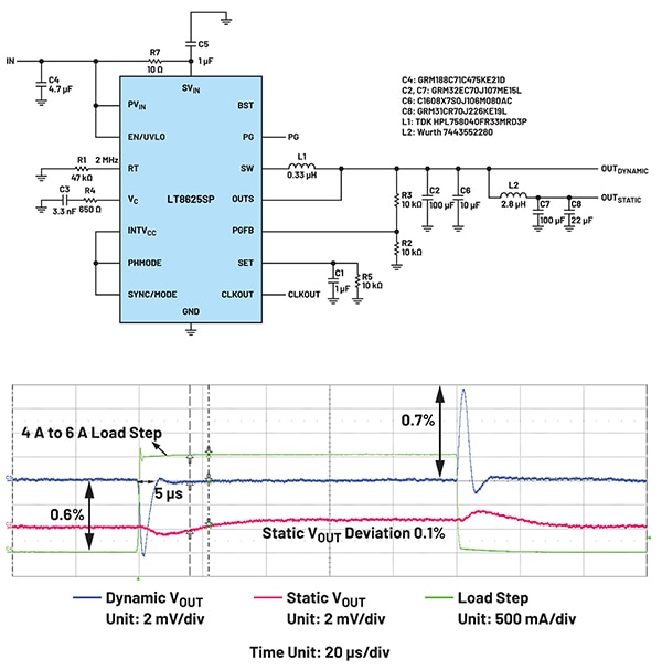
The high-bandwidth feature of these devices enables designers to power the two critical 1 V load groups from a regulator IC by separating the dynamic and static loads with a second inductor (L2) (Figure 2, top). The load transient response is fast, with minimal VOUT deviation, and will not affect the static load (Figure 2, bottom).
Figure 2: Shown is an application circuit for the Silent Switcher that separates the dynamic and static RF loads with an inductor (L2) for enhanced performance (top); the load transient response is fast with minimum VOUT deviation and will not affect the static load (bottom). (Image source: Analog Devices)
Postfiltering with a minimized equivalent inductance - In time division duplex (TDD) mode, the noise-sensitive LOs and VCOs are loaded and unloaded with the transmit/receive mode changes. Thus, a simplified circuit can be used since all the loads are considered dynamic; at the same time, more critical postfiltering is required to maintain the low ripple and noise features for the LOs and VCOs.
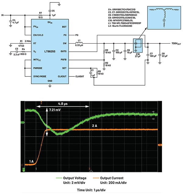
A three-terminal capacitor in feedthrough mode can achieve sufficient post-filtering with minimal equivalent inductance, thereby maintaining a fast bandwidth for load transients (Figure 3, top). The feedthrough capacitor, together with the remote side output capacitors, forms two additional inductor-capacitor (LC) filter stages. All the inductance is due to the equivalent series inductance (ESL) of the three-terminal capacitor, which is very small and less harmful to the load transient. The feedthrough capacitor enhances transient response while minimizing output voltage ripple (Figure 3, bottom).
Figure 3: Shown is an application circuit for combined dynamic/static RF loads that uses a three-terminal feedthrough capacitor (upper right corner) to provide postfiltering with minimal equivalent inductance to maintain a fast bandwidth for the load transients. The feedthrough capacitor enhances transient response while minimizing output voltage ripple (bottom). (Image source: Analog Devices)
Precharging - In some cases, the signal-processing unit has general-purpose I/O (GPIOs); also, the signal processing is scheduled, and the transient event is known in advance. This typically occurs in some FPGA power-supply designs, where the precharge signal can be generated to help power the supply’s transient response.
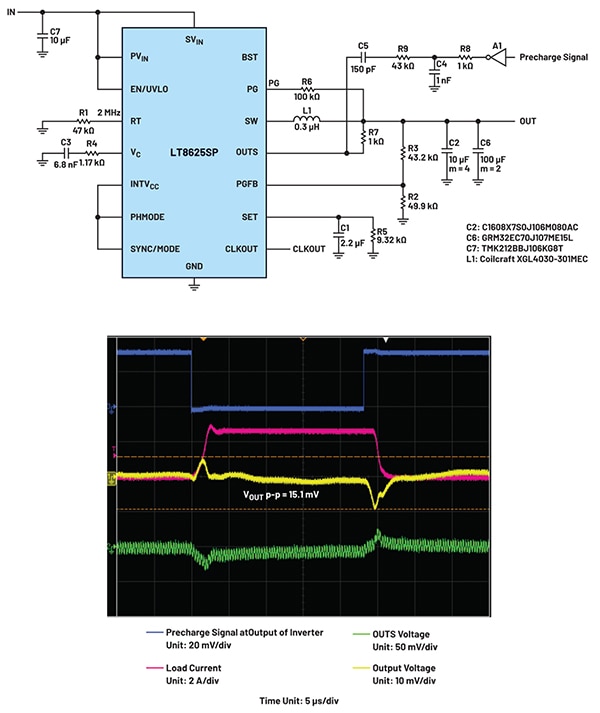
In a typical application circuit (Figure 4, top), if the FPGA generates a precharge signal to provide a bias before the real load, the transition allows the device to have extra time to accommodate the load disturbance with minimal VOUT deviation and recovery (Figure 4, bottom).
Figure 4: Shown is a precharge signal fed into an error amplifier’s negative input pin (OUTS) to yield a fast transient response; the regulator’s feedback is affected by both the precharge signal and the load transient (bottom). (Image source: Analog Devices)
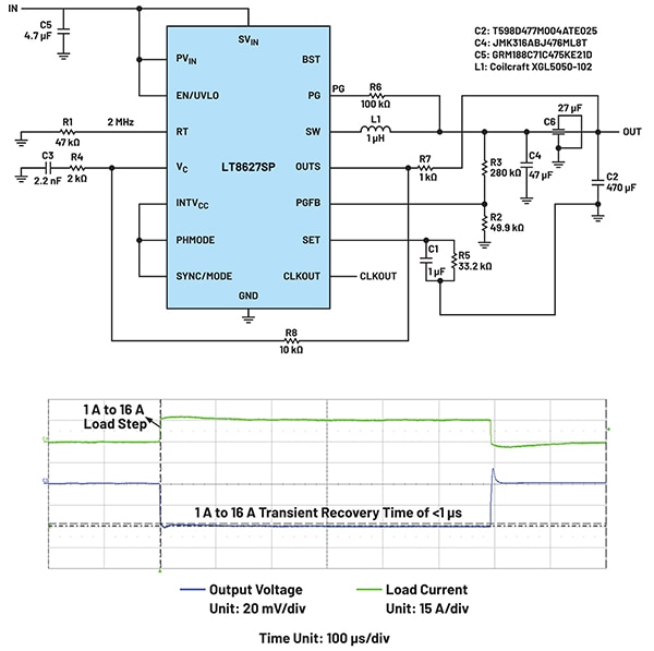
Active drooping - In beamformer applications (Figure 5, top), the supply voltage continuously changes to accommodate different power levels. As a result, the accuracy requirement for the supply voltage is usually 5% to 10%. In this application, stability is more important than voltage accuracy, as minimizing recovery time during the load transient maximizes data-processing efficiency. A drooping circuit is a good fit for this application as the drooping voltage will reduce or even eliminate the recovery time (Figure 5, bottom).
Figure 5: Placing an active drooping resistor (R8) between OUTS and VC helps achieve a fast transient recovery (top); droop transient response can be tailored to minimize the transient recovery time (bottom). (Image source: Analog Devices)
Devices implement and validate the innovations
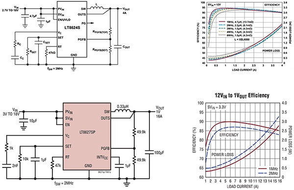
These noise-reduction and transient-improvement concepts have been incorporated into the family of monolithic Silent Switcher 3 devices. They support a wide range of voltage and current maximums, while offering users flexibility and performance without compromise. Two examples make this clear: the LT8622SAV#PBF (Figure 6, top) and the LT8627SPJV#TRPBF (Figure 6, bottom).
At the lower end of the current and power range, the LT8622SAV#PBF is a 2 ampere (A) continuous-output switcher for inputs from 2.7 V to 18 V. It has an output voltage range of 0 V to VIN - 0.5 V that can be programmed with a single resistor. Efficiency over most of its output-current range is at least 90% and reaches 95%.
Figure 6: Shown is the 2 A LT8622 in a typical application configuration, along with its efficiency and power-loss curves (top) (note: the LTC8624 in the schematic is identical to the LT8622 with the same curves but has a 4 A rating); the same information for the 16 A LT8627 is also shown (bottom). (Image source: Analog Devices)
The LT8622SAV#PBF offers exceptional low-frequency (0.1 Hz to 100 kHz) output noise performance in a switching regulator, with an RMS noise of just 4 μVRMS. The operating frequency is adjustable and can be synchronized from 300 kHz to 6 MHz. The device is housed in a small 20-lead 4 mm × 3 mm LQFN package.
The higher-power 16 A LT8627SPJV#TRPBF has an input voltage of 2.8 V to 18 V, while the output voltage is resistor-adjustable from 0 to VIN - 0.5 V. Efficiency exceeds 80% and reaches 90% in the mid-range sweet spot at a 1 MHz switching frequency. Its low-frequency output noise performance is the same as that of the 2 A LT8622SAV#PBF.
The operating frequency is also adjustable and can function and be synchronized from 300 kHz to 4 MHz, which is lower than that of its lower-current sibling. Its package is a slightly larger 24-lead 4 mm × 4 mm LQFN with an exposed back for an optional heatsink.
Conclusion
Designers of innovative products, especially in the leading-edge RF area, require efficiency, but it must be accompanied by low noise and a fast transient response on the supply voltage. The Analog Devices Silent Switcher 3 family of DC/DC regulators is the next generation of high-efficiency monolithic devices optimized for noise-sensitive, dynamic load-transient performance across multiple applications.

免责声明:各个作者和/或论坛参与者在本网站发表的观点、看法和意见不代表 DigiKey 的观点、看法和意见,也不代表 DigiKey 官方政策。