Implementing USB 3.0 in MCU- and Microprocessor-Based Systems
投稿人:电子产品
2013-02-20
USB is among the most ubiquitous of interfaces in microcontroller (MCU) and microprocessor-based systems. However, the technical thought behind USB has always centered more on ease of use and compatibility — in other words, the plug-and-play experience — than on performance. The new USB 3.0 standard finally delivers a true high-performance bus, topping out at 5 Gbit/s rates, while maintaining backward compatibility and the required plug-and-play functionality. With ICs and components rolling into the marketplace featuring USB 3.0 support, design teams should consider adding support for the new flavor to their projects – whether they are working on a general-purpose host or peripherals, or relying on USB in a specialty embedded application.
The case for USB 3.0 is clear in the PC world. Most new PCs will integrate USB 3.0 ports now that Intel has included the feature in its newest Ivy Bridge processor and chipset platform, referred to as the third-generation Intel Core family. If you are working in the PC host area, there are numerous options for adding USB support, which we will discuss shortly. You should consider that approach even if your processor of choice does not support USB 3.0, and whether your design targets either IT or embedded usage. The performance could come in handy down the road as more USB 3.0 peripherals hit the market.
If you are working on a USB 3.0 peripheral, again you should consider USB 3.0 support. That advice is especially pertinent is you are working on storage- or connectivity-oriented devices where USB performance has been a bottleneck.
In the embedded space, USB 3.0 will also come in handy. Many embedded applications need storage devices such as traditional disk drives, or the solid-state disk drives that are surging in popularity. USB 3.0 will significantly enhance the performance of such devices at the system level. Moreover, USB 3.0 will support higher-fidelity sensing devices such as higher-resolution cameras for applications ranging from visual inspection on the factory floor to target tracking in a UAV (unmanned aerial vehicle).
USB 3.0 basics
Before we get into the enabling components that you can use in USB 3.0 designs, let us quickly discuss what is new. USB 1.1 was the first shipping version of the interface supporting 1.5 Mbit/s Low Speed and 12 Mbit/s Full Speed modes. USB 2.0 arrived more than a decade ago and added a 480 Mbit/s High Speed mode. Now, USB 3.0 adds the 5 Gbit/s Super Speed mode.
USB 3.0, however, includes a much bigger shift in the technology that underlies the interface than the evolutionary version number uptick might imply. Essentially, USB 3.0 is really two buses in one. USB 3.0 hosts, hubs, and peripherals will include the legacy signals that comprise USB 2.0. The USB 3.0 implementations add two new pairs of wires that carry the full-duplex 5 Gbit/s data. USB 3.0 connectors may look familiar, but they hide additional signaling pins, which come into play when you pair a USB 3.0 host and device.
USB 3.0 also overcomes a fundamental performance limitation of earlier versions. USB 1.1 and 2.0 rely on the host to continuously poll all connected devices to see if any peripheral has data that needs to be transmitted. USB 3.0 adds an asynchronous notification capability that allows peripherals to signal the host when they need the bus.
The change in protocol is significant in terms of both realized performance and power consumption. USB 2.0 devices typically delivered only around 30% of the maximum bandwidth due to the polled nature of the interface. The USB Implementers Forum has said that USB 3.0 should deliver at least 3.2 Gbits/s rates, characterized at the system level.
The new protocol also means USB 3.0 devices do not have to remain powered at all times to answer the host polling. In a link with a USB 3.0 host and peripherals, the peripherals can enter and remain in low-power states for extended periods.
Of course, in the PC world, we are likely to have a mixed environment of USB 3.0 and USB 2.0 devices. Such a mix may prevent, in some cases, full realization of the USB 3.0 benefits. However, in an embedded system, the design team can potentially ensure the use of USB 3.0 exclusively. That would allow a design to both maximize performance and minimize power consumption – virtually always requirements for embedded system design.
If you would like more information on USB 3.0, see the MCU TechZone article entitled, "USB 3.0: Are We There Yet."
USB 3.0 host controller
Now we will move on to a discussion of available ICs that you might turn to in USB 3.0 system designs, starting with host controllers. Texas Instruments (TI) offers a pair of host controller ICs, the two-port TUSB7320RKMR and the four-port USB7340RKMR (Figure 1). Both these ICs rely on a one-lane (x1) PCI Express (PCIe) Gen2 connection to the host processor, and on the USB side seamlessly support USB 2.0 or USB 3.0 downstream devices.
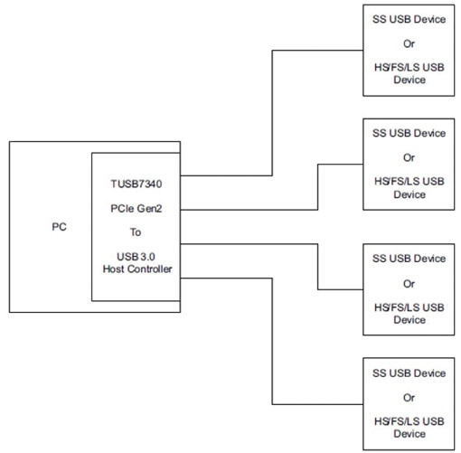
Figure 1: The TI USB7340RKMR host controller IC links host processor with a PCIe Gen2 bus to USB 3.0 or USB 2.0 peripherals.
The ICs integrate the functionality typically required in USB host controller (xHCI) designs. The controller includes a default configuration that will work with USB Mass Storage Class (MSC), Human Interface Device (HID), and Communication Devices Class (CDC) peripherals. Optionally, you can add serial flash memory if you need to support custom peripherals. The IC generates the required spread-spectrum modulation, internally, for the faster USB 3.0 data transfers.
You can easily deploy the TI controller ICs with any host processor that includes a PCIe Gen2 expansion bus. Many such applications would be in systems based on the x86 processor and PC architecture, whether the application at hand was embedded or IT centric. TI says, however, that it expects the controller ICs to find usage in applications such as set-top boxes, gaming consoles, and smart TVs. The greater bandwidth in USB 3.0 devices makes the bus capable of handling HD video streams in such applications.
Peripheral controller IC
Moving to the peripheral side of the link, Cypress Semiconductor was among the first to market with USB 3.0 silicon. The CYUSB3014-BZXI USB 3.0 peripheral controller IC integrates an ARM926EJ core that supports clock speeds as fast as 200 MHz. You will also see Cypress refer to the IC as the EZ-USB FX3.
Figure 2 includes a block diagram of the Cypress IC. There are a number of ways to interface external components to the peripheral controller IC. As you can see along the bottom of the block diagram, the IC includes a number of serial interfaces. The UART operates as fast as 4 Mbits/s. The I²C interface operates at a maximum 1 MHz. The Serial Peripheral Controller (SPI) interface operates at a maximum 33 MHz. The I²S audio-centric interface is transmit only and supports sampling rates as high as 48 kHz.
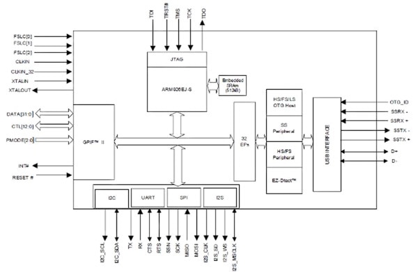
Figure 2: Cypress integrates an ARM9 core and a number of typical MCU serial interfaces on its CYUSB3014-BZXI USB 3.0 peripheral controller IC.
Cypress also integrated what it calls the General Programmable Interface (GPIF II) that supports 8- to 32-bit parallel connections with clock rates as fast as 100 MHz. The II designator in the name reflects that the interface is a next-generation version of the GPIF implementation that Cypress used on USB 2.0 peripheral controller ICs. Indeed, design teams that used the GPF previously and developed external circuitry for the interface should be able to reuse that work. Cypress also offers the GPIF II Designer Tool that allows you to configure the on-chip state machines to support standard and proprietary interfaces to external devices such as a Compact Flash memory device.
The integrated ARM core will be able to handle many USB 3.0 peripheral applications without the need for an additional MCU or microprocessor. The IC integrates 512 Kbytes of SRAM memory, as well as data and code caches. You can boot the processor via USB, I²C, SPI, or the GPIF II. That flexibility means that the boot code can be stored in devices ranging from low-cost serial flash to a disk drive to memory connected to an auxiliary processor. When your application requires a secondary processor, you can easily interface an MCU to the GPIF II in master or slave modes, and you can support external memory in the same manner.
Cypress suggests that the peripheral controller is a good fit for next-generation USB 3.0 peripherals such as video and still cameras, printers, and scanners – all of which require transmission of rich media streams. The company also identified a number of specialty embedded applications such as medical imaging, machine vision, and surveillance where USB 3.0 will enable new levels of image fidelity.
Application-specific SOCs
The performance potential of USB 3.0 will surely lead to a broad selection of application-specific SOC devices soon. Although the technology is surely young, the first such SOCs are hitting the market, such as TI's TUSB9261PVP USB 3.0 to SATA-II bridge IC. You can use the IC to quickly design a product such as a USB 3.0-connected external disk drive. Applications that are more complex include portable media players that integrate either magnetic or solid-state storage.
Figure 3 depicts the IC architecture. TI based the IC on an ARM® Cortex-M3 core. Essentially the device is an application-specific MCU. It integrates memory and a host of I/O capabilities including USB 3.0 and SATA II. The device first tries to connect to a host via USB 3.0. If that connection fails after a training-sequence time out, the IC will then enable a USB 2.0 connection at the maximum speed supported by the host.
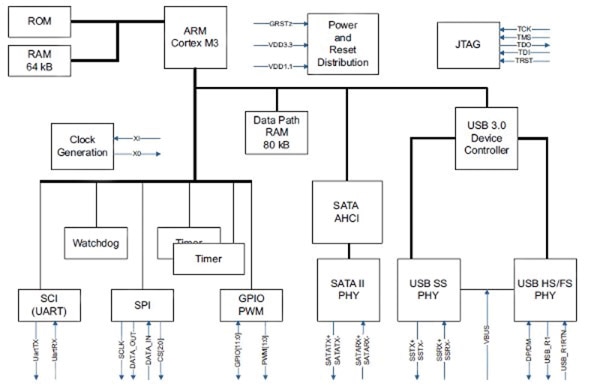
Figure 3: Offering a bridge between USB 3.0 and SATA II, the TI TUSB9261PVP is based on an ARM Cortex-M3 and can handle applications such as portable media players that integrate mass storage.
In reality, design teams can use the TTUSB9261PVP in any application in which the capabilities are a fit. While TI supplies built-in support for applications such as an external disk drive, the design team does have the ability to program the Cortex-M3. You can load custom code into the core via SPI-connected memory.
USB 3.0 hub ICs are another example of application-specific functionality. As with earlier versions of USB, hubs are required building blocks for the tiered-star topology of the bus. TI offers the TUSB8040PFP USB 3.0 4-port hub IC for such applications. The IC essentially integrates both a USB 2.0 hub and a USB 3.0 hub. It supports either version of the interface both upstream to a host and downstream to peripherals.
Figure 4 shows the versatility of the hub IC. You can see how the design seamlessly supports USB 1.1 devices downstream. Moreover, a system can comprise a mix of USB 2.0 and USB 3.0 hubs as well as devices.
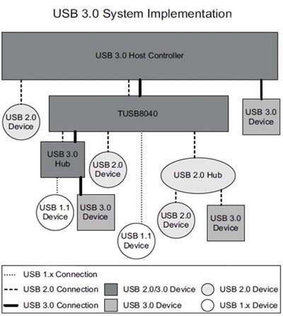
Figure 4: A USB 3.0 hub IC such as the TI TUSB8040PFP must include both USB 2.0 and USB 3.0 hub functionality to enable upstream and downstream connections to devices based on any flavor of the ubiquitous USB standard.
We are also starting to see other support ICs emerge for USB 3.0 designs that ultimately simplify the task of delivering subsystem- and system-level products. For example, Pericom offers the PIEQX7741/42 USB 3.0 line driver ICs. Also referred to as ReDrivers, the ICs include programmable equalization that can ensure a product's ability to connect over the 3 m maximum cable length for USB 3.0 connections. The Pericom ICs support the two signal pairs required for two USB 3.0 ports.
Similarly, TI offers ReDriver functionality in the SN65LVPE502RGER USB 3.0 line driver IC. The IC handles a single USB 3.0 port and offers programmable equalization, de-emphasis, and output-swing control.
Connectors, cables, and hubs
Having covered the IC space, we should discuss other components required for an actual USB 3.0 design before we conclude. You might think that elements such as connectors and cables are relatively low-tech and barely worth a detailed look, but with USB 3.0, the connector and cable situation changed quite a lot. Remember, as we discussed up front, USB 3.0 is really two interfaces in one. You will not get the benefits of USB 3.0 without specifically using connectors designed for the new standard.
TE Connectivity provides a good example for us to dig into as the company supplies the bulk of the connectors you might need in a system. The host side of a USB link uses the slim USB connector that we are most familiar with such as the one on a USB mouse. That connector is referred to as a Type A connector. For the host side of such a link, TE connectivity offers the 1932258-1 USB 3.0 A-type receptacle that is general soldered down on a PCB (Figure 5). The 1932355-1 USB 3.0 stacked 2-port A-type receptacle offers two receptacles for dual-port implementations.
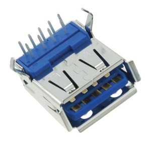
Figure 5: The TE Connectivity 1932258-1 USB 3.0 receptacle is designed to be soldered onto the PCB in a USB 3.0 host application.
For the cable side of the host connection, TE Connectivity offers the 1932266-1 USB 3.0 plug. USB peripherals, such as external disk drives, use a different type of connector referred to as a Type B connector. TE Connectivity offers the 1932259-1 USB 3.0 B-type receptacle for such products.
A number of other companies offer USB 3.0 connectors in a variety of configurations. The list includes available product from Amphenol, Assmann WSW Components, CNC Tech, EDAC, Hirose Electric, JAE Electronics, and Würth Electronics.
Several sources offer USB 3.0 cables including Würth. CNC Tech offers both USB 3.0 Type A to Type A cables and USB 3.0 Type A to Type B cables.
USB 3.0-enabled hubs will likely be broadly available soon. If you need one to use in your development project, Assmann WSW Components offers the DA-70230-1 USB 3.0 4-port hub.
Conclusion
The good news is that, despite a lengthy development process, USB 3.0 is here and there is little reason you should not consider the technology for you next design. Indeed, the technology may be even more valuable for embedded specialty systems than for the PC world. USB 3.0 can effectively connect higher-fidelity peripherals to systems such as an HD camera that might target aerial-surveillance or medical applications. If you can use all USB 3.0 devices in a system, you will realize lower system power than you can with USB 2.0. USB 3.0 may cost a bit more, for now, but you get what you pay for in faster transfer rates for applications that need such performance.
免责声明:各个作者和/或论坛参与者在本网站发表的观点、看法和意见不代表 DigiKey 的观点、看法和意见,也不代表 DigiKey 官方政策。


