Creating a Miniaturized Analog Controlled Servo
投稿人:DigiKey
2012-03-21
Position control on a small scale
Advanced position control systems have been used in industrial control applications for decades. Often these systems are complex and expensive, as well as necessary. In today’s electronic marketplace options exist that allow for very small and inexpensive position control systems. It is now possible to affordably provide advanced control systems on a small scale, and even customize multiple designs around a fixed piece of electronic hardware. This creates many options for enhanced manufacturing control, which in turn reduces material loss and saves time and money. This article describes a simple design that was later built upon to create a powerful miniaturized motion control system.
A Miniaturized Servo Controller
Using Microchip’s dsPIC family of 16-bit microcontrollers allows for sophisticated control schemes to be developed with very low hardware costs. For this application, the dsPIC33FJ64MC802-I/MM-ND part was selected as an appropriate controller. Significant reasons for the selection of this part are as follows:
- 64K x 8 of flash based memory, 16K x 8 RAM
- Free evaluation version of MPLAB C from Microchip
- Low cost debugger/programmer via MPLAB ICD3
- Up to 40MIPS operating speed
The robust Freescale MC33926PNB-ND was selected to provide an interface between the microcontroller and the DC motor in this servo design. However, virtually any H-bridge IC could be inserted into this design, allowing the motor size to be easily scaled once the control system is perfected. The MC33926PNB was selected for the following reasons:
- Fault and load current feedback is available on the IC
- Operates from 5 to 28 VDC
- PWM signal up to 20 KHz is possible
- Multiple internal protections including short circuit
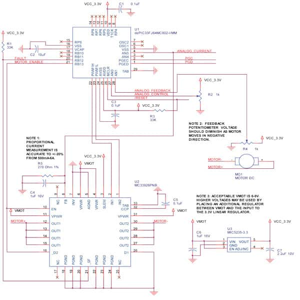
Previously we discussed the major parts selected to create a miniaturized servo system. To provide more detail, we will design a closed-loop proportional controller based on these parts (see Figure 1). Using the dsPIC33 AD and PWM modules, we can quickly produce a 12-bit analog control and analog feedback system. Additional money can be saved by using the internal RC oscillator and PLL to operate at a speedy 36.85 MIPS, with a 250 µS control loop.
The dsPIC33 firmware will also monitor the fault and current feedback from the H-bridge IC. If a fault condition exists, the microcontroller will attempt to reset the H-bridge at every control loop. If the motor load current exceeds approximately 2 A, the dsPIC33 firmware will turn off the PWM signal.
Operating the dsPIC33 PWM module at 20 KHz allows for a PWM value between 0 (0% duty cycle) and 3685 (100% duty cycle). This is nearly 12-bits of resolution, and closely matches our 12-bit analog measurements. The PWM signal is generated by multiplying the error signal (analog control measurement – analog feedback measurement) by a proportional term constant. Selecting the proportional term value was done by trial and error, and a variety of values provided smooth control.
PWM Output = Proportional Term * (Analog Control – Analog Feedback)
The PWM output must be limited to no more than +3685 and no less than -3685 to keep it within the boundary of the PWM module’s 100% duty cycle value (at 20 KHz). This is also handled in the firmware.
In addition to protections built into the MC33926PNB-ND, the load current is monitored to shut the motor down if it exceeds approximately 2 A. The MC33926PNB-ND provides a proportional feedback current of 0.24% of the motor’s load current. A 270 ohm resistor converts the feedback current to a voltage that is monitored by the dsPIC33. At 2 A, this voltage is 1.296 V, or 1608 bits with the 12-bit AD on the dsPIC33 (3.3V/4096 = 0.805mV per bit). The feedback current is a gross measurement, with an accuracy of only ±20% above 500 mA. However, it is still useful for protecting the control system.

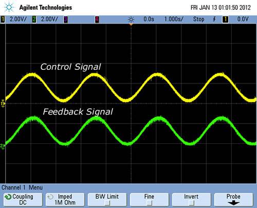
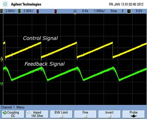
When testing this design, we used a Pittman GM9236S025-R1 12 V gearhead motor with a 65.5:1 gear ratio. The gear ratio prevented fast response, as shown in the following ramp waveform test signal (Figure 3), but otherwise created a powerful servo system. Feedback was delivered via a potentiometer attached directly to the motor shaft. The 12 V motor voltage was stepped down by a 5 V linear regulator (not shown in schematic), which in turn supplied power to the on-board 3.3 V linear regulator.


Physical prototype
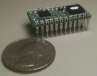
The prototype for this design was placed into a 24 pin, 600 mil wide, DIP package (Figure 4). The 2-layer board was routed to include a serial communication port, connections for limit switch inputs, a quadrature encoder port, and the ability to read pulses from 5 µs to 20 ms in duration.
Also routed on the board are connections to allow for debugging with a variety of Microchip’s tools. This design was completed using the MPLAB ICD3 debugger/programmer.

Firmware
The firmware for this design was written using a free evaluation version of Microchip’s C30 C compiler (version 3.25). The MPLAB IDE version 8.66.00.00 was used as a development environment. Debugging and programming was accomplished using the MPLAB ICD3 running on firmware revision 1.26.52.
The firmware listed here performs a simple motion control system with analog control input and analog feedback. Proportional control, as well as over-temperature, over-current, and under-voltage protection, are implemented, either in firmware or hardware. The firmware, provided below, can be used as a starting point for more complex systems using the same hardware.
In fact, this hardware is used to implement a full PID control algorithm with a serial command interface and a variety of control and feedback options. This design is currently being manufactured by Solutions Cubed, LLC as the Synaptron Micro Motion Controller.
//--------------------------------------------------------------------
//
//--------------------------------------------------------------------
// The following files should be included in the MPLAB project:
//
// synaptron_opensource_01.c -- Main source code file
// traps.c -- Explicit definitions of dsPIC33F Traps
// p33FJ64MC802.h -- Header file for dsPIC
// p33FJ64MC802.gld -- Linker script file
//--------------------------------------------------------------------
// Revision History
// 1/10/12 -- synaptron_opensource_01.c -- initial implementation
//--------------------------------------------------------------------
#define FCY 36850000ULL
#include "p33FJ64MC802.h" // register an bit definitions are here
/*********************************************************************
CONFIGURATION BITS AND DEFINE STATEMENTS
*********************************************************************/
/* oscillator setup */
_FOSCSEL(FNOSC_FRCPLL & IESO_OFF);
_FOSC(FCKSM_CSDCMD & OSCIOFNC_ON & POSCMD_NONE & IOL1WAY_OFF);
/* power-on-reset */
_FPOR( PWMPIN_ON & HPOL_OFF & LPOL_OFF & ALTI2C_OFF & FPWRT_PWR32)
/* watchdog timer */
_FWDT(FWDTEN_ON & WINDIS_OFF & WDTPRE_PR32 & WDTPOST_PS64);
/* code protection */
_FBS(BWRP_WRPROTECT_OFF);
_FSS(SWRP_WRPROTECT_OFF);
_FGS(GWRP_OFF);
/* program/debug */
_FICD(ICS_PGD1 & JTAGEN_OFF);
/* Application Define statements, variables, constants */
#define FAULT PORTBbits.RB12
#define ENABLE PORTBbits.RB13
#define PWMSTATE_STOPPED 0x0000
#define PWMSTATE_FORWARD 0x0201
#define PWMSTATE_REVERSE 0x0102
unsigned int AnalogControl = 0;
unsigned int AnalogFeedback = 0;
unsigned int AnalogCurrent = 0;
unsigned int ProportionalTerm = 0;
int PWMOutput = 0;
/*********************************************************************
INITIALIZATION ROUTINES
*********************************************************************/
/*********************************************************************
Function: InitTimer5
Description: Initialize Timer5 for a 250uS timer without interrupts
*********************************************************************/
void InitTimer5( void )
{
T5CON = 0; // ensure Timer 5 is in reset state
IFS1bits.T5IF = 0; // reset Timer 5 interrupt flag
IPC7bits.T5IP = 5; // set Timer5 interrupt priority level to 5
PR5 = 9212; // set Timer5 period register
T5CONbits.TCKPS1 = 0; // select Timer5 Input Clock Prescale 1:1
T5CONbits.TCS = 0; // select external timer clock
T5CONbits.TON = 1; // enable Timer 5 and start the count
IEC1bits.T5IE = 0; // disable Timer 5 interrupt
}
/*********************************************************************
Function: InitPLL()
Description: Initializes the oscillator and PLL settings and waits for lock. Processor will run at 36.85MIPS.
*********************************************************************/
void InitPLL()
{
// 7.37MHz / 2 * 40 / 2 FCY = FOSC/2 = 36.85MIPS
CLKDIVbits.PLLPRE = 0; //N1 = 2 VCO divider = /2
PLLFBDbits.PLLDIV = 38; //40x multiplier
CLKDIVbits.PLLPOST = 0; //N2 = 2 PLL input divider = 2
while(OSCCONbits.LOCK != 1);
}
/********************************************************************* Function: InitIO()
Description: Initializes pin directions(input/output) and voltages.
*********************************************************************/
void InitIO()
{
TRISAbits.TRISA0 = 1; // Control voltage input
TRISAbits.TRISA1 = 1; // Feedback voltage input
LATA = 0xFFFF;
TRISBbits.TRISB2 = 1; // unused
TRISBbits.TRISB3 = 1; // Current voltage input
TRISBbits.TRISB4 = 1; // unused
TRISBbits.TRISB5 = 1; // unused
TRISBbits.TRISB6 = 1; // unused
TRISBbits.TRISB7 = 1; // unused
TRISBbits.TRISB8 = 1; // unused
TRISBbits.TRISB9 = 1; // unused
TRISBbits.TRISB10 = 1; // unused
TRISBbits.TRISB11 = 1; // unused
TRISBbits.TRISB12 = 1; // FAULT input
TRISBbits.TRISB13 = 0; // ENABLE output
TRISBbits.TRISB14 = 0; // PWM1L output
TRISBbits.TRISB15 = 0; // PWM1H output
LATB = 0x1FFF;
}
/*********************************************************************
Function: InitADC()
Description: Initialize ADC module for 12-bit operation with
*********************************************************************/
void InitADC( void )
{
AD1CON1 = 0; // Clear control registers
AD1CON2 = 0;
AD1CON3 = 0;
AD1CHS0 = 0x0000; // Channel select AN0
AD1PCFGL = 0xFFFF; // Analog inputs configured as digital
AD1PCFGLbits.PCFG0 = 0; // AN0 analog
AD1PCFGLbits.PCFG1 = 0; // AN1 analog
AD1PCFGLbits.PCFG5 = 0; // AN5 analog
AD1CON1bits.AD12B = 1; // 12-bit, 1 channel operation
AD1CON1bits.FORM = 0; // Integer result
AD1CON1bits.SSRC = 0; // Clearing sample bit starts conv.
AD1CON1bits.ASAM = 0; // Sampling when sample bit is set
AD1CON2bits.CSCNA = 0; // Disable channel scanning
AD1CON2bits.VCFG = 0; // AVDD and AVSS are references
AD1CON3bits.ADRC = 0; // Clock derived from system clock
AD1CON3bits.ADCS = 0x2f; // ADC conversion clock
AD1CON1bits.ADON = 1; // Turn on ADC module
}
/********************************************************************
Function: void InitMCPWM(void)
Description: Initialize motor control pulse-width modulation module to 20KHz.
********************************************************************/
void InitMCPWM(void)
{
P1TCON = 0x8000; // PWM as free running mode, 1:1 TCY
PWM1CON1 = 0x0111; // Enable PWM1L and PWM1H
// configure them for independent mode
PWM1CON2 = 0x0000; // achieving 20 kHz
P1DTCON1 = 0x0028; // 2 us of dead time
P1DTCON2 = 0x0000;
P1FLTACON = 0x0000; // Initialize Fault Controls
PTPER = FCY/20000 - 1; // Compute Period
P1OVDCON = PWMSTATE_STOPPED; // Disable PWM1 outputs.
P1DC1 = 0; // Set duty cycle to 0
}
/*********************************************************************
PROGRAM ROUTINES
*********************************************************************/
/*********************************************************************
Function: ReadAnalog()
Description: Collects analog values and performs proportional multiplication of the error signal. Also measures the motor current and shuts down the motor drive if it exceeds 2A +/- 20%.
*********************************************************************/
void ReadAnalog(void)
{
unsigned int SampleTime = 0;
AD1CHS0 = 0x0000; // Channel select AN0 (pin RA0)
AD1CON1bits.SAMP = 1;
while (SampleTime < 100) // Provide >5uS for sample time
SampleTime++;
AD1CON1bits.SAMP = 0;
while(!AD1CON1bits.DONE);
AnalogControl = ADC1BUF0; // Store conversion in register
AD1CHS0 = 0x0001; // Channel select AN1 (pin RA1)
AD1CON1bits.SAMP = 1;
SampleTime = 0; // Provide >5uS for sample time while (SampleTime < 100)
SampleTime++;
AD1CON1bits.SAMP = 0;
while(!AD1CON1bits.DONE);
AnalogFeedback = ADC1BUF0; // Store conversion in register
AD1CHS0 = 0x0005; // Channel select AN5 (pin RB3)
AD1CON1bits.SAMP = 1;
SampleTime = 0; // Provide >5uS for sample time while (SampleTime < 100)
SampleTime++;
AD1CON1bits.SAMP = 0;
while(!AD1CON1bits.DONE);
AnalogCurrent = ADC1BUF0; // Store conversion in register
ProportionalTerm = 10; // Set proportional value
PWMOutput=(int(ProportionalTerm*(AnalogControl-AnalogFeedback));
// Ensure PWM signal does not exceed 100%
if (PWMOutput > 3685)
PWMOutput = 3685;
if (PWMOutput < -3685)
PWMOutput = -3685;
if (AnalogCurrent > 1600) // 1600 is approximately equal to 2A.
PWMOutput = 0;
}
/*********************************************************************
Function: MotorControl()
Description: This subroutine checks for fault conditions and if a fault is present disables the H-bridge. If there is no fault condition the H-bridge module is configured for the appropriate direction and the PWM signal in PWMOutput is applied to the motor. Note that the PWM value is inverted to apply the appropriate output signals, and if a fault occurs the H-bridge is re-enabled after the control loop timer elapses.
*********************************************************************/
void MotorControl(void)
{
if (FAULT == 0) // Fault input 0V during fault condition
{
PWMOutput = 0; // Disable motor output if fault occurs.
ENABLE = 0; // Disable H-bridge
}
if (PWMOutput>0)
P1OVDCON = PWMSTATE_FORWARD; // Set for forward
if (PWMOutput<0)
{
P1OVDCON = PWMSTATE_REVERSE; // Set for reverse
PWMOutput = -PWMOutput; // Invert PWM signal
}
if (PWMOutput == 0)
P1OVDCON = PWMSTATE_STOPPED; // Stop H-bridge
P1DC1 = 3685 - PWMOutput; // Set PWM value
}
/*********************************************************************
MAIN PROGRAM
*********************************************************************/
int main(void)
{
InitPLL(); // Initialize the PLL, wait for lock
InitIO(); // Initialize i/os
InitADC(); // Initialize ADC
InitTimer5(); // Initialize a timer
InitMCPWM(); // Initialize PWM
while (1)
{
asm("clrwdt"); // Clear watch dog timer
if (IFS1bits.T5IF == 1) // Check control loop timer
{
IFS1bits.T5IF = 0; // Clear flag for next loop
ENABLE = 1; // Enable H-bridge
ReadAnalog(); // Take analog readings
MotorControl(); // Set PWM drive signal
}
}
}

免责声明:各个作者和/或论坛参与者在本网站发表的观点、看法和意见不代表 DigiKey 的观点、看法和意见,也不代表 DigiKey 官方政策。


