Carrier Signal Powered EEPROM Cuts the Wires
投稿人:电子产品
2013-06-05
Energy harvesting, in its broadest sense, is a huge area of technology; it can encompass geothermal, solar, wind, heat-recovery, and other ambient energy capture techniques, and require installations covering many square miles and costing millions of dollars. However, very small energy-harvesting (EH) implementations also are attracting a very high level of interest today; these are designs that allow handheld devices and remote modules to gather power freely from their local environment, thereby eliminating the need for frequent battery recharging or running long power lines. These developments are affecting consumer designs (smartphones, for instance), industrial applications (wireless sensor networks), commercial operations (inventory control), medical systems (drug control), and more.
As a result of this interest, we are beginning to see new components come to market that are designed to simplify implementation of small EH systems. One such recently introduced device is the M24LRxxE-R series dual-interface EEPROM from STMicroelectronics. While it also works via an I²C interface and a VCC power supply, of major interest here is its ability to operate as a contactless memory, powered by RF energy harvested from a received carrier signal.
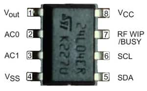
The EEPROM is available in three versions: the 4-bit M24LR04E (Figure 1), the 16-bit M24LR16E, and the 64-bit M24LR64E. The EEPROM’s memory bank can be accessed by an ISO 15693 / ISO 18000-3 RF reader operating at a carrier frequency of 13.56 MHz. The memory can sustain a data rate up to 53 kbits/s over a distance of 1 m. The communication capability more than meets the requirements for near-field communication, or NFC, which is becoming a popular function in new smartphones. The EEPROM also provides the status of RF operations and has the ability to provide harvested energy to other devices, as well as supporting high-security applications with a 32-bit password protection mechanism.
EEPROM operation
When used in I²C mode, the two-wire (bidirectional serial data, SDA, and clock, SCL) interface works in typical fashion, communicating with a microcontroller or other such device to control the EEPROM in slave mode.
For use in RF mode, the memory must be connected to an antenna on its AC0 and AC1 pins. Then, an incoming 13.56 MHz carrier can address the memory, from which it demodulates the data encoded on the signal using amplitude-shift keying (ASK). In this mode, the memory harvests energy, deriving its operating power from the RF energy of the incoming signal; no external power supply is required.
In accordance with the ISO standards, the received ASK wave is 10 percent or 100 percent modulated with a data rate of 1.6 kbits/s using the 1/256 pulse-coding mode or a data rate of 26 kbits/s using the 1/4 pulse-coding mode. Outgoing data is generated by the chip using load variation and Manchester coding, with one or two subcarrier frequencies: 423 and 484 kHz. Data is transmitted at 6.6 kbits/s in low-data-rate mode and 26 kbits/s in high-data-rate mode. The EEPROM also supports a 53 kbit/s fast mode in high-data-rate mode using the 423 kHz subcarrier.
In the energy-harvesting RF mode, the chip can even output energy derived from the RF field that is in excess of what it needs to operate. The excess energy is delivered through the chips VOUT analog output pin, and if the RF field strength is insufficient, VOUT goes into high-Z state and external energy harvesting is automatically stopped.
The EEPROM also has a user-configurable digital output pin, RF WIP/BUSY, that can signal when RF operations are taking place, provided the EEPROM is powered through its VCC pin. The pin can be used to drive a microcontroller interrupt pin when either of two user-selected scenarios occur: in the RF write-in-progress (WIP) mode, the RF WIP/BUSY pin is driven low for the entire duration of the RF internal write operation; in the RF busy mode, the pin is driven low for the entire duration of the RF command progress.
Providing the antenna needed for the chip involves a bit of board design work. STMicroelectronics offers an Application Note¹ that provides both the theory and practice for building on-board antennas of various shapes – circular, rectangular, spiral, and so forth.
Putting an EH EEPROM through its paces
Even so, designing and etching an antenna onto a board requires considerable effort when you just want to evaluate how the chips perform. Fortunately, there is a fast easy and inexpensive way to become familiar with this device’s full operating characteristics: the M24LR-Discovery evaluation kit. The kit consists of two boards, one red and one green, that are essentially all the components you need to put the EEPROM through its paces, and the boards allows you to observe and control the signals during operation with external instruments and signal sources. Control/demo software and documentation are available for free download.² You will need to supply a USB master/slave cable to connect to your PC, which runs the software.
The 4 kbit M24LR04E-R dual-port EEPROM is on the red M24LR board (Figure 2), along with other needed or useful components: an STM8L152C6T6 8-bit microcontroller with 8 Kbytes of flash memory, an STTS751-0WB3F low-voltage digital temperature sensor, a 20 x 40 mm inductive antenna etched on the PCB, two function buttons (User and Reset), a SWIM connector for programming and debugging, I²C connectors, and a 24-segment, 4-common LCD.
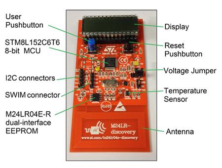
In addition to communicating with the green RFID reader board discussed below, the M24LR board can also work by itself with Android NFC phones that support ISO/IEC 15693. An application called NFCV-Reader is available for free download from the Google Play app store. STMicroelectronics notes that, depending on NFC phone's RF management, performance may vary.
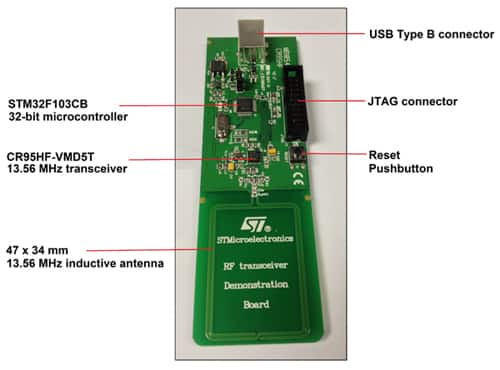
The green board (Figure 3) is an RFID reader demonstration board that provides, among other parts, a multi-protocol CR95HF 13.56 MHz contactless transceiver IC with SPI and UART serial access. Connected to a PC using a USB cable with Type A and B male connectors, this board is controlled by the downloaded demonstration software running on the PC.
Hands on experience
After downloading and installing the PC software, which was simple, I set up the two boards as seen in Figure 4, so that the antennas overlapped. When I plugged the USB connector into my PC, a red LED on the green board came on to show me I had made a connection to the red board. Moving the boards apart horizontally caused the light to go out, but with only a slight overlap of the antennas, the signal was strong. On the other hand, the boards could be vertically separated by about 1.5 in. or so, and the signal was still good enough to keep the red board powered up.
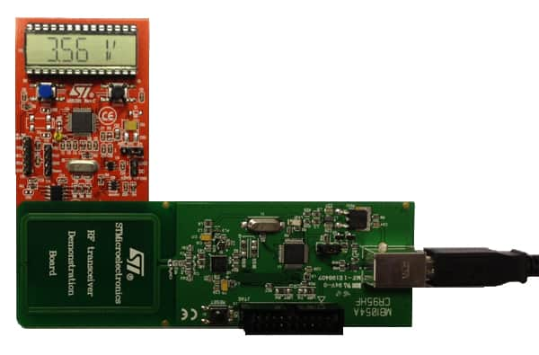
The display on the red board also came on, showing the internal voltage of the energy-harvesting M24LR; which is how I could tell how strong the signal was. Once the red board is powered, a program pre-stored in flash memory will display voltage; it can also display the ambient temperature measured by the on-board sensor, and any text message that is stored in the EEPROM (initially, the EEPROM is blank). Pressing the blue User button will cause the display to cycle through these three sets of information.
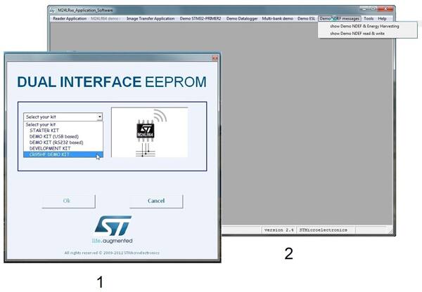
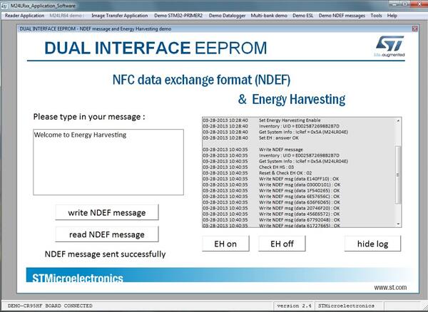
To interact with the red board wirelessly, I launched the downloaded program. The first thing I had to do was select the particular demo I wanted to run (the software supports several different evaluation kits), as seen in Figure 5. From the drop-down menus on the next screen, I selected “show NDEF & Energy Harvesting”. (NDEF is the acronym for NFC Data Exchange Format.) This opened the screen shown in Figure 6.
A very useful feature of the software is that it allows you to see a log of the information transferred between the two boards. As seen in Figure 6, the first four lines of the log show the transmission that took place when I initially clicked on the “EH on” button. The following lines show the transmission that took place after I typed in the phrase “Welcome to Energy Harvesting” and clicked on the “write NDEF message”. Sure enough, the message appeared on the red board’s display.
One thing I noticed was that, if messages were longer than 50 characters, the display would not show it, which may be a limitation of the firmware. However, there was no problem with the memory’s operation; when I clicked on the “read NDEF message” after powering down and powering up again, the full message came through:
Smartphone connection
My last experiment was getting a smartphone with NFC capability to talk with the memory. Using a Samsung Galaxy III, I downloaded and installed the NFC-V reader app from Google Play. When I booted the app and held the phone over the red M24LR board, the board’s display indicated that I had made a good connection. The app was able to read the hardware parameters of the board without a problem (Figure 7).
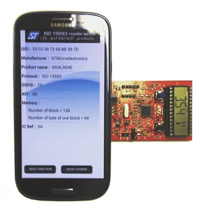
Writing and reading to the board presented some difficulty with this phone, because standards for tag data formats are in the process of undergoing some changes. Google and Samsung have developed a format that they want to use, and the Android OS is designed to work with this format at a very high level. However, moves are afoot among NFC standards committees to broaden the way software will handle different tag formats. In the near future, this difficulty should disappear.
In conclusion, I would say that working with the kit was a generally pleasant experience, and one that was well supported with such documentation as circuit diagrams, bills of materials, datasheets, and application notes. I look forward to continuing to explore the EEPROM’s capability in greater detail in the future.
References
- Application Note AN2972, Designing an antenna for the M24LRxx-R and M24LRxxE-R dual interface I²C/RFID devices.
- M24LR-Discovery control/demo software and documentation: www.st.com/m24lr04e-discovery
免责声明:各个作者和/或论坛参与者在本网站发表的观点、看法和意见不代表 DigiKey 的观点、看法和意见,也不代表 DigiKey 官方政策。


