目录
返回顶部
Resistors
Ohm Law
Resistor Attributes
Resistor Types
Surface Mount
Through Hole
Chassis Mount
Resistor Network
Potentiometers, Variable Resistors
Capacitors
Ceramic
Film
Aluminum Electrolytic
Tantalum
Electric Double Layer Capacitors (EDLC), Supercapacitors
Inductors
Core Types
Inductor types
Wirewound
Molded
Multilayer
Passives
A passive electrical component is a circuit element that does not generate power but either dissipates power or captures, stores energy in the form of a magnetic or electrical field and release it back to the circuit as electrical voltage or current.
Passive circuit elements include resistors, capacitors and inductors. When used in schematic drawings are typically labeled as R, C, and L respectively. Passive elements in a circuit are used individually or as part of a networked connected to other passive components. They may also be connected to active components such as semiconductor devices to control signals or provide feedback but cannot increase the power of an electrical signal
Resistors
Resistors are one of the most common passive circuit components. Resistors are used in nearly every circuit for tasks like reducing voltage, limiting current, attenuating signals, acting as electrical load and dividing voltages.
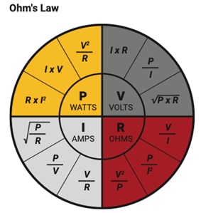
Ohm Law
A resistor operates by resisting or limiting the flow of electrical current through the resistor, given a voltage difference between the two terminals of the resistor. The relation between voltage, electrical current, and resistance can be described by Ohm’s Law.
Ohm's Law, formulated by Georg Simon Ohm in the early 19th century, is one of the basic principles in electronics. It states that the current (I) flowing through a conductor between two points is directly proportional to the voltage (V) across those two points, and inversely proportional to the resistance (R) of the conductor. Mathematically, Ohm's Law can be expressed as:
V = I ⋅ R
- Voltage (V) - measured in volts (V), represents the electrical potential difference between two points in a circuit. It is the driving force that propels electric charge through a conductor.
- Current (I) - measured in amperes (A), is the flow of electric charge through a conductor. Ohm's Law states that the current is directly proportional to the voltage, meaning an increase in voltage results in a proportional increase in current, assuming resistance remains constant.
- Resistance (R) - measured in ohms (Ω), is the opposition that a material offers to the flow of electric current. As per Ohm's Law, if the voltage across a resistor is constant, increasing the resistance will decrease the current flow, and vice versa.
- Power (P) - measured in watts (W), represents the rate at which energy is transferred in a circuit
 Sourced from: https://media.digikey.com/pdf/Innovation%20Handbook/Formulas-Laws-and-Equations.pdf
 DigiKey has free calculators for many essential electronics calculations including for Ohm's Law.
Resistor Attributes
- Resistance – measured in the unit of Ohms, impedes or regulates the flow of current.
- Tolerance - amount of variation either above or below the stated resistance value.
- Power - maximum steady state power dissipation under specified test condition measured in Watts.
Resistor Types
Surface Mount
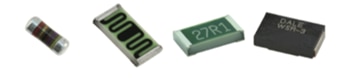
Surface Mount resistors are the small brick like resistor components that are either attached by solder connection or adhesive application to the surface of a printed circuit board. Due to the small size and lack of external leads, humans typically don’t work with surface mount components, but it can be a fun challenge to try: https://www.digikey.com/en/products/detail/chip-quik-inc/SMDPST120/15195098
Through Hole
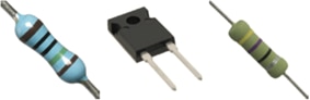
Through Hole resistors are resistor components with wire lead termination designed to be fitted and soldered in place on a circuit board. While the larger size makes through hole resistors easier to work for humans, the larger body also takes up more space on a circuit board making placement difficult at times. The wire leads and nature of soldering makes through hole components more difficult for automated assembly machines.
Chassis Mount
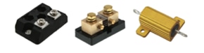
Chassis Mount resistors are the larger standalone resistor components that are fixed to the chassis or enclosure of the device and are not found on a circuit board. Chassis mount resistors typically have much higher power dissipation than resistors that reside on a circuit board.
Resistor Network
Resistor Networks are multiple interconnected resistors inside the same package. Resistor networks include resistors in series (where all resistors are connected end to end in a line) and/or in parallel (where resistors are connected side by side).
Potentiometers, Variable Resistors
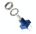
Potentiometers, often referred to as "pots" are three terminal passive resistors-based devices that can vary the amount of resistance. The most common method a potentiometer can vary the output resistance by physically moving a wiper arm across a length of resistive material, the longer the distance from the input terminal the higher the resistance.

Resistor eBook
The goal of this resource is to aid the reader in making informed resistor selections by explaining differences in device construction, how those differences affect non-ideal resistor behaviors, and how these differences are communicated in product literature and parametric search tools
Conversion Calculators
DigiKey's online conversion calculators offer a one-stop resource for many electronics industry calculations. Whether you are identifying a 4 band resistor or trying to determine battery life, DigiKey can help you get the answers you need.
LEARN2SOLDER
The DigiKey LEARN2SOLDER Kits are meticulously designed for individuals who are taking their first steps into the world of soldering, making them an excellent choice for beginners eager to grasp the fundamentals of this essential skill.

How to Select a Resistor for an LED
Without a limited current flow, LEDs will eventually fail. Sometimes catastrophically. For most cases, this is solved by simply adding a resistor (of appropriate size) in series with the LED.
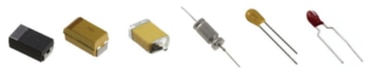
Capacitors
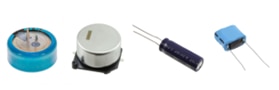
A capacitor is a passive two terminal device that stores energy in an electric field, formed between conductive electrodes separated by an insulating material called a dielectric. The traits of different dielectric materials contribute to the varying characteristics of different capacitor types that are available. Many capacitors are named in reference to the dielectric material used.
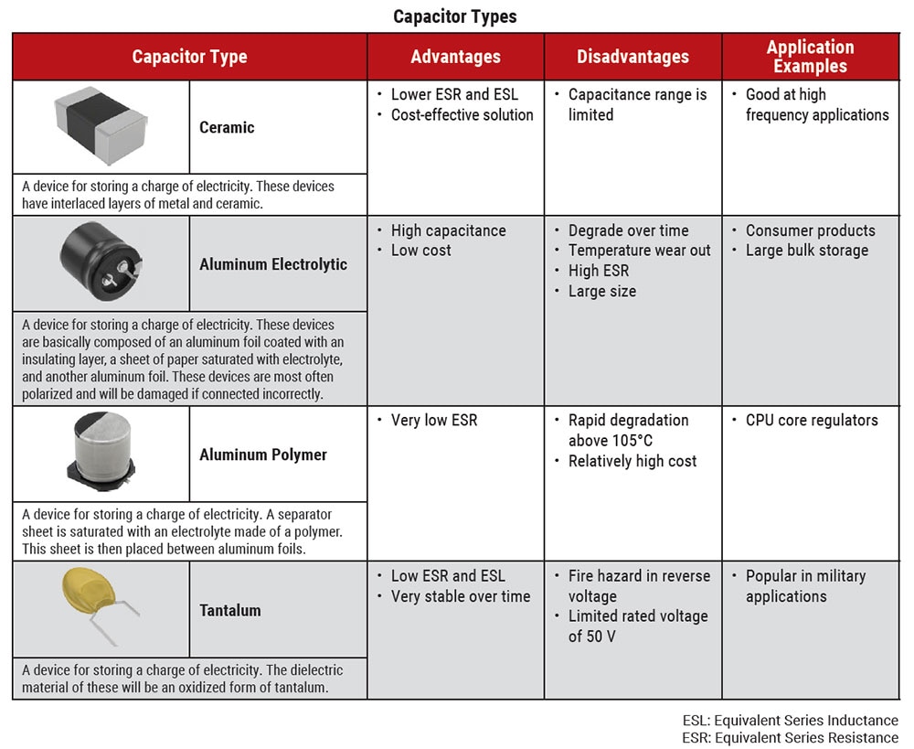

Ceramic
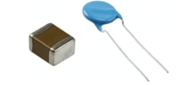
The most common type of capacitor manufactured today. Ceramic capacitors are made up of one or more stacked layers of ceramic material acting as the dielectric and metal layers as the electrodes. One of the cheapest types of capacitors (per unit) and are found in most consumer electronics today, with applications from power filtering to signal conditioning.
Film
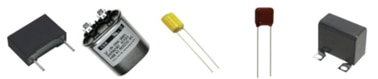
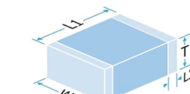
As the name suggests Film Capacitors are made from layers of plastic film stacked on top of one another with layers of metallic foil or other plastic film with metal applied directly to one side. Due to the plastic film construction, they have higher voltage ratings, lower series resistance, and good stability over temperature ranges.
Aluminum Electrolytic
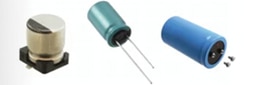
Aluminum Electrolytic capacitors, also called aluminum capacitors are some of the most common electrolytic capacitors. They have high capacitance value, small package size, and higher cost (per unit). However, due to poor electrical properties of high ESR, low operating temperature range, and short service life measured in Aluminum capacitors are often used in bulk applications where accuracy is not necessary.
Tantalum
The name comes from Tantalum being used in the electrode. The electrolyte in a tantalum is (usually) a solid material rather than a fluid as in the case of aluminum capacitors. This allows for a much greater energy storage density with a reduced component footprint and longer service lifespan then aluminum capacitors.
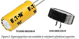
Electric Double Layer Capacitors (EDLC), Supercapacitors
The latest developments in capacitor materials have led to devices with capacitance values measured in whole units of Farads instead of millionths or billionths of farads. Super capacitors can be thought of as the middle ground between regular capacitors and rechargeable batteries offering quick discharge rates.
Capacitors eBook
Capacitor attributes include physical and chemical makeup which results in ideal and non-ideal characteristics for a given use. This guide’s learning section explores these characteristics such as equivalent series resistance (ESR) and inductance (ESL), leakage, polarization, aging and dielectric absorption
Choosing the Right Capacitor Technology for an Application
Selecting the right capacitor type is crucial in product design. Three common options—multilayer ceramic capacitors (MLCCs), film, or aluminum electrolytic—offer advantages and disadvantages, and there are myriad variations within each category.
Understanding Supercapacitors and Their Relationship with Batteries
Electric double-layer capacitors (EDLC), or supercapacitors, offer a complementary technology to batteries. Where batteries can supply power for relatively long periods, supercapacitors can quickly provide power for short periods.
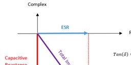
Calculating capacitor ESR from Tan(δ)
Capacitor equivalent series resistance (ESR) is often a characteristic of interest, that is not directly specified in parametric data or a device datasheet. Information about a device’s loss angle (δ) is usually available in these cases, which allows calculating an ESR value.
Inductors
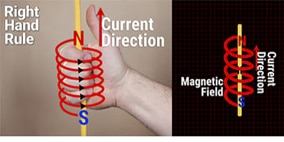
Inductors store energy like capacitors, however they store energy in a magnetic field generated when electrical current passes through the inductor wiring. In terms of construction, an inductor is a length of conducting wire that has been shaped into a spiral or wrapped around a central core. The central core is typically made of air, plastics, ceramics, or ferromagnetic material.
Core Types
For the cores of inductors there are two main types, magnetic cores, those made up of iron or ferrite materials, and non-magnetic cores, those that are made up of ceramic, plastic, polymer, or air cores that do not affect the magnetic field generated by the energized coil.
- Magnetic cores – are built around or have the central area filled with a material that has high magnetic permeability such as iron or ferrite compounds. These high magnetic permeability materials can dramatically increase the magnetic field density of a given part making small inductors have greater values then an equivalent nonmagnetic core type. These are used in higher value inductors (those over 1 uH).
- Non-magnetic cores - do not affect a magnetic field in which they are placed. When used as inductor cores, they primarily provide mechanical support for the windings rather than participating in the device’s magnetic circuit. Lack of a magnetic core material restricts the amount of inductance that can be achieved in each physical space but avoids core losses and saturation, so devices based on nonmagnetic core materials are mostly low inductance (<1uH) devices with comparably good Q factors, high-frequency performance, linearity, and stability. They commonly are used in RF and signal applications where minimizing non-ideal behaviors is of more importance than the ability to store large amounts of energy.
Inductor types
Wirewound
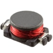
As the name suggests, wire wound inductors are simply wire wound around a central core shape.
Molded
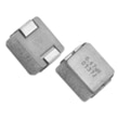
Molded inductors have the core material shaped and formed around the wire wound core.
Multilayer
Multilayer inductors are constructed somewhat like multilayer capacitors with layers of conductive and insulating materials are stacked.
eBook - Fixed Inductors
An introduction to selecting fixed Inductors, also known as coils or chokes, which are electronic components that store energy in a magnetic field and oppose any change in the current that passes through them.
Video – What is an inductor?
Inductors are one of the most common electronic components in the industry, right up there with resistors and capacitors. While they may seem simple, there’s more to consider about them than just their size and inductance value.


