Part 18: Types of Modeling in Verilog
2025-06-16 | By DWARAKAN RAMANATHAN
Introduction:
Verilog is a hardware description language (HDL) used for designing and simulating digital systems. It allows designers to describe circuits at various levels of abstraction, which helps in reducing complexity during the design phase. Verilog provides several types of modeling techniques, each suited for different purposes. In this tutorial, we’ll explore the three primary types of Verilog modeling: Behavioral Modeling, Dataflow Modeling, and Structural Modeling.
1. Behavioral Modeling:
Behavioral modeling describes the functionality of the circuit without detailing its internal structure. It enables designers to write high-level descriptions that allow for faster prototyping and debugging. Here, designers describe what the circuit should do, not how it should be implemented.
Key Characteristics:
- Describes what the system does.
- Abstracts away the internal structure and timing details.
- Frequently employs constructs such as always, initial, and assign.
- Suitable for preliminary designs or functional simulation.
Example:
A simple 2-to-1 multiplexer is defined using Behavioral modeling.
module mux2to1 (input wire a, b, sel, output wire out);

   assign out = (sel)? b : a;

endmodule
In this example, the assign statement is used to specify the output out based on the value of the selection signal sel. If sel is 1, the output will be b; otherwise, it will be a.
2. Dataflow Modeling:
Dataflow modeling describes the movement of data in the system and determines the logic functions between different signals. It is opposite to Behavioral modeling, which only emphasizes functionality; instead, it emphasizes the movement of data from one component to another using logical operators.
Key Features:
It describes how data flows through the system.
It focuses on logical operations and connections.
assign statements are used for continuous assignments.
It is typically used for combinational logic circuits.
Example:
Here is an example of a 4-bit AND gate using dataflow modeling.
module and_gate_4bit (input [3:0] a, b, output [3:0] out);

   assign out = a & b;

endmodule
In this example, the assign statement repeatedly computes the bitwise AND of inputs a and b, storing the result in out. Dataflow modeling makes it easy to represent logic gates, arithmetic operations, and more complex data manipulations.
3. Structural Modeling:
Structural modeling describes the system at the gate level and states how different parts, such as gates and registers, are interconnected to make up the overall system. This method is the closest to the hardware implementation because it discusses how the hardware is actually made.
Key Characteristics:
- Describes the structure of the system.
- Concerned with the interconnection of gates, modules, and other components.
- Uses instantiation to refer to pre-defined modules or gates.
- Good for detailed circuit design and synthesis.
Example:
A full adder modeled structurally would look like this:
module full_adder (input a, b, cin, output sum, cout);

   wire s1, c1, c2;

   xor (s1, a, b);

   xor (sum, s1, cin);

   and (c1, a, b);

and (c2, s1, cin);

 or (cout, c1, c2);

endmodule
Here, we instantiate logic gates (`xor`, and, or) and connect them to form the full adder's sum and carry output. This is a low-level description, focusing on the exact gates used in the design.
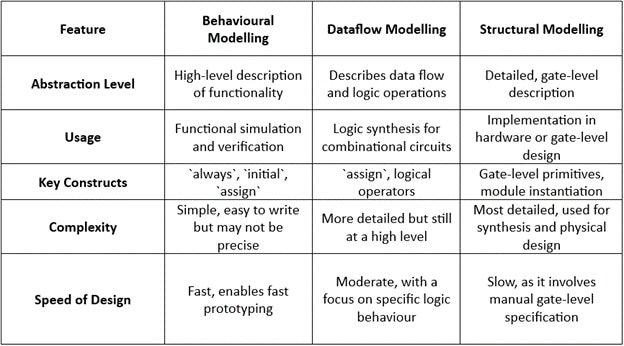
Key Differences Between the Three Modeling Types:

Advanced Verilog Features: Enhancing Modeling Capabilities
The above three modeling styles form the basics of Verilog design, though there are also some more enhanced features that allow increasing the expressiveness and efficiency in your designs.
1. Task and Function
Verilog facilitates defining tasks and functions in order to maintain modular design as regards reusable code blocks. Functions represent the combinational logic returning a value, while the tasks can provide multiple outputs along with the permission of procedural execution.
Example of a function to calculate a square:
function [7:0] square;

    input [3:0] in;

    square = in * in;

endfunction
2. Generate Constructs:
The generate statement is used when you want to create repeating hardware structures. This is usually the case if you need to instantiate multiple copies of a module, or if you want to replicate a particular logic somewhere.
Example of generating 8 instances of a 2-to-1 multiplexer:
genvar i;

generate

for (i = 0; i < 8; i = i + 1) begin : mux_block

        mux2to1 u_mux (.a(a[i]),.b(b[i]),.sel(sel[i]),.out(out[i]));

    end

endgenerate
3. FSM Modeling:
Finite State Machines (FSM) are widely used in Verilog to model sequential logic. You can use case statements within always blocks to describe different states and transitions.
Example of a simple Moore FSM:
module fsm (input clk, reset, output reg out);

    reg [1:0] state, next_state;


    // State encoding

    parameter S0 = 2'b00, S1 = 2'b01, S2 = 2'b10;


    // Next state logic

    always @ (state or reset)

        if (reset) next_state = S0;

else case (state)

            S0: next_state = S1;

            S1: next_state = S2;

            S2: next_state = S0;

default: next_state = S0;

        endcase

    // State update logic

    always @ (posedge clk or posedge reset)

        if (reset) state <= S0;

        else state <= next_state;


// Output logic

    always @ (state)

        case (state)

            S0: out = 0;

            S1: out = 1;

            S2: out = 0;

default: out = 0;

        endcase

endmodule
Conclusion
Verilog offers various modeling techniques in designing digital systems, which differ according to specific purposes. Modeling is suited to the development phase and functional simulation for Behavioral modeling, to combinational logic for dataflow modeling, and is essential for the implementation of gate-level designs by structural modeling. It is with such knowledge and usage of modeling types that you are able to successfully design efficient and reliable hardware systems.
As you continue to gain more knowledge of Verilog, you will continue to explore features such as tasks, functions, generate constructs, and FSM modeling so that you may design more complex circuits and improve the performance of your designs.


