制造商零件编号 28009
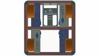
EXPERIENTIAL ROBOTICS PLATFORM (
SparkFun Electronics
License: See Original Project LIDAR Proximity Raspberry Pi MCU
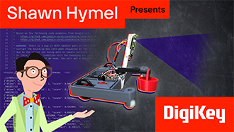
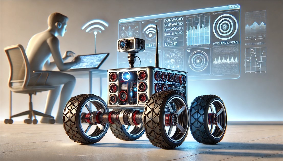
Imagine a fragile house of cards sitting on a table. Now imagine a robot I built, equipped with a LiDAR sensor, driving at full speed directly toward it. If I have done everything correctly, it should stop before it hits the cards and back up safely. But first, do you remember last time, when we explored the basics of LiDAR and how it sees the world in 360 degrees? Today, I want to actually build something with it. I want my XRP robot to map its surroundings, avoid obstacles, and maybe even warn me when I am getting too close.
Here is the plan: I want to control the robot using a game controller. I also want to use LiDAR for object detection and, if possible, get the controller to vibrate when the robot is too close to an object. It sounds simple, but I know that integrating these components will definitely lead to some problems. I have questions about connecting the sensor to the XRP, whether to use hardware or software serial, and how to mount the sensor on the platform. I also need to figure out whether the game controller will actually work with the MicroPython libraries on the Raspberry Pi Pico 2 W.
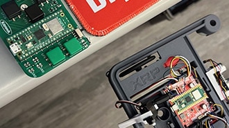
First, we need to plan the connection of the XRP and the LiDAR sensor. The XRP controller runs a Raspberry Pi Pico 2 W, which has three serial ports. One is the port routed through the USB connector and used for serial print statements in your code. To find the other two, I looked at a pinout diagram. I could see that one serial port was on GPIO pins 0 & 1, while the other was less clear. It looked like it could either be GPIO pins 4 & 5 or 8 & 9. To test this, I wrote a two-line Arduino sketch to begin serial communication at 115200 baud and repeatedly write the hex value A5. By probing the pins with an oscilloscope, I confirmed that serial one is on GPIO 0 & 1. For serial two, I found data being transmitted on GPIO pin 8, and that tells me that serial two is on GPIO pins 8 & 9. Both sets of pins are accessible via the expansion headers or the servo connectors on the XRP platform. I chose the servo connectors because they also provide ground and five volts.
Next, I had to handle the data flow from the LiDAR sensor. As the LiDAR sensor spins, it sends packets of measurement data. Each packet contains five bytes. The packet breakdown information is outlined in the LiDAR datasheet. The first byte has the measurement quality, a start bit, and a complement of a start bit. The second and third bytes contain the angle measurement and a check bit. The fourth and fifth bytes combine to give the distance. Parsing this data while keeping the packets synchronized was a challenge. I had to check each byte as it entered the serial buffer to ensure that the start bits, the complement to the start bit, and the check bits were in the correct state. I used a serial peek technique, which allowed me to check the contents of the next byte without removing it from the buffer. Once I found a valid starting byte, I could read the next 4 bytes and parse them into distance and angle measurements. To limit the amount of data processed, I filtered the data to show only angles near zero, which would be in front of the robot. To validate this code, I used a measuring tape and placed a white lid at 600 millimeters, and the sensor reported 603 millimeters. That is very accurate for this type of setup.
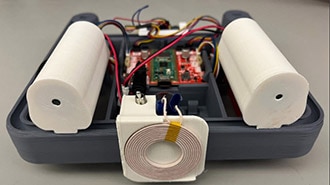
Now that the LiDAR sensor is working and sending clean data to the XRP platform, and I can see objects around the room in real time, I can move on to the really fun part: making the robot move with the gaming controller! From what I understand, it is possible to use the controller directly with the XRP platform, but it requires a computer as a middleman. I wanted the robot to run on the robot without needing a computer. There is a library called BluePad32 that works well with game controllers, but it is primarily designed for ESP32-based microcontrollers. While the documentation does suggest it can work on a Raspberry Pi Pico 2 W, it is complicated to do so. My solution was to use an ESP32 as a bridge. The ESP32 receives game controller input and sends speed commands to the XRP via a serial UART protocol. I loaded the library onto a Xiao ESP32, and the controller paired perfectly. I could see the joystick and trigger values changing on my screen. I wrote more code for the XRP to accept controller data from the ESP32 and made a wiring harness to connect them. Finally, after designing and 3D printing a custom mount to secure the LiDAR sensor and the extra electronics, the robot was officially finished.
It was time for the real test. I started with a large DigiKey box. I drove the robot straight at it, and it stopped, backed up, and my controller vibrated. It worked so well that the robot would not even let me drive into the box. Next, I tried a coffee cup, which should be a little harder for the LiDAR to see, and the sensor did its job. I was unable to drive into it.
The final challenge was the house of cards... I have to admit, building a house of cards is much harder than building a robot. I spent an hour trying to get just two layers high and eventually had to use a few dabs of hot glue to keep it standing. To be honest, I would rather get credit for building an obstacle-avoiding LiDAR robot than for building a house of cards. At full throttle, I drove the robot at the cards. It detected the obstacle, stopped just in time, and backed up, buzzing. This worked perfectly!
I basically gave my robot a sense of self-preservation. We went from a bare robot to one with a spinning laser that can detect the world and avoid obstacles. This project was harder than I expected, but very rewarding. If you want to build one yourself, all the design files are available on Maker.io.
Download all design files for this project from the GitHub repo https://github.com/bytesizedengineering/XRP-RPLIDAR