Custom Pseudo-Neon Sign Writing with Flexible LED Noodle Filaments
2025-05-01 | By Kitronik Maker
License: See Original Project Laser Cutters Other Optoelectronics
Courtesy of Kitronik
Guide by Kitronik
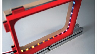
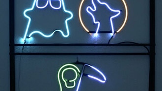
The LED noodles first crossed our threshold in February, so naturally there was Valentine's inspiration in the air when this “Pseudo-Neon” sign was born.
This make was developed by Becky and Geoff from the development team for the Fernwood School Design Day in January 2025 and is designed so that you can easily customise your own noodle and diffuser design.
This Make Covers:
We Used:
Kitronik Flexible LED Noodle Filaments USB lamp kit - 5 pack.
Matte Black 3mm Value Acrylic.
Red 5mm Fluorescent PERSPEX®.
2 x 10mm M3 Pan Head Screws.
3 x 8mm M3 Plastic Spacers.
7 x M3 Hex Nuts.
30cm of Rigid Wire (for planning the shape).
Some Thin Copper Wire.
Some String.
1 - Check out the DXF!
This is a nice simple dxf with only two components - the pegboard and the heart-shaped diffuser.
2 - Laser cut your pegboard diffuser!
While we find it best to make the pegboard from a black material (we used the matte black Value Acrylic) you can experiment with the colour and finish of both that and the diffuser. Our make’s diffuser is made from red Fluorescent PERSPEX®.
3 - Soldering the kit together!
Solder on the switch, the resistor, the USB lead, and the separate red and black wires. Use these notes to help you!
Note: The black wire will be the negative wire and will therefore be soldered onto the pad closest to the flat edge of the LED outline.
4 - Plan your noodle’s shape, then form it!
We used a 30cm piece of wire - the same length as the noodle - to plan the shape before moving on to forming the noodle itself.
To secure the shape, we used small lengths of copper wire and looped them over the noodle, through two holes on the pegboard, and then twisted the ends on the back of the pegboard like a twist tie. The best positioning for these ties is at the apex of curves or corners in your design.
5 - Solder the noodle to the PCB!
Tuck the two ends of the noodle through the pegboard and solder the ends to their respective wires. Red is positive and will therefore be soldered to the tab with the tiny hole in it (see picture).
6 - Mount the PCB on the back of the pegboard:
Using two 10mm M3 pan head screws and 4 M3 hex nuts, line up the mounting holes on the PCB with two holes on the pegboard and mount as shown. Two of the hex nuts should be screwed on first to act as small spacers, before the PCB and then the second two hex nuts to hold the PCB down.
7 - Affix the diffuser to the front of the pegboard:
Using three 16mm M3 pan head screws, three 8mm plastic spacers and three M3 hex nuts, attach the diffuser as shown in the image.
8 - (Optional) - Add a string!
Add string to make it a wall hanging!
©Kitronik Ltd – You may print this page & link to it but must not copy the page or part thereof without Kitronik's prior written consent.