制造商零件编号 SC0326
RASPBERRY PI CM4IO BOARD
Raspberry Pi
License: Attribution Raspberry Pi SBC
The Raspberry Pi Compute Module 4 (CM4) was announced in October. It contains many of the same specifications as the original Raspberry Pi 4, but it does away with most of the connectors, opting for a couple of 100-pin, high-density Hirose connectors on the underside. Rather than be an affordable desktop placement like the traditional Raspberry Pi, the CM4 is intended for industrial applications where the module is embedded into a custom PCB and enclosure.
There are several options available for the CM4, with and without built-in WiFi, and with varying degrees of RAM and flash. There is also an official carrier board (the CM4IO) for the CM4 that breaks out most of the IO lines and signal buses.
The CM4 IO expansion board is a useful “kitchen sink” development board, but for that amount of money, why not just get a regular Raspberry Pi 4? The real power of the CM4 lies in its small form factor. With a little KiCad knowledge and some patience to solder your own PCB, you can make the CM4 into whatever form factor you want!
If you are not familiar with KiCad, I recommend starting with this video series:
https://www.youtube.com/watch?v=vaCVh2SAZY4&list=PLEBQazB0HUyR24ckSZ5u05TZHV9khgA1O
If you would like to get started by watching the schematic capture portion of the CM4 carrier board, you can watch the video here:
CM4IO KiCad files
To start, know that Raspberry Pi made their official CM4IO board completely open source. You can download the KiCad design files here (CM4IO-KiCAD.zip). I recommend starting there to see how they created individual sections of the carrier board, and you can use them in your own design--picking and choosing just the sections you need!
IMPORTANT! The CM4IO project (and custom carrier boards found in this post) require KiCad version 6.0 or later. If 6.0 is not out, you can use the nightly pre-release found here. Choose your OS and scroll down to the “nightly build” section. There may be bugs in nightly builds.
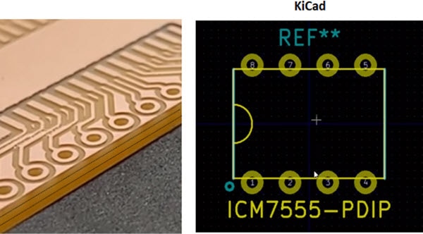
Open up the KiCad project and the associated schematic. You should see that the project uses hierarchical sheets.
Double-click on one of the blocks (sheets) to navigate into that sheet. For example, if you go into the GPIO section, you can see that one of the Hirose connectors is broken out into the standard Raspberry Pi GPIO header, an Ethernet port, SD card, and some LEDs.
You can copy and paste various sections from this example schematic into your own schematic. You are also welcome to use the symbol library (.kicad_sym) file and footprint library (.pretty folder) that came with the CM4IO project in your own project.
This can help you save a lot of time and ensure that the footprints will work with the CM4!
Carrier Board Template
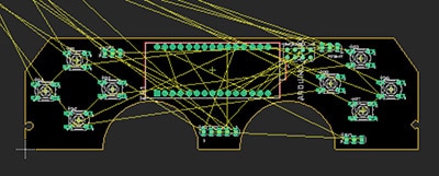
To help you get started creating your own carrier board, I put together a KiCad template (schematic and PCB layout) for a basic board that connects to the Raspberry Pi CM4.
You can download that template from my GitHub repo here: https://github.com/ShawnHymel/rpi-cm4-carrier-template
This project contains a copy of the CM4IO libraries (schematic and footprint) and gives you a basic CM4 footprint as a starting point.
Note that the board edge is the same as the CM4’s silkscreen outline. Feel free to move the outline (Edge.Cuts layer) to any shape or size you desire (so long as you can still mount the CM4 to your board).
With the template, there are no headers or pins broken out; it’s just a starting point for your project.
Example Project: Base Carrier
In addition to the carrier template board, I also put together a sample project that can be used to break out some of the IO lines on the CM4. Once again, feel free to use it as a starting point!
You can download the base carrier design files here: https://github.com/ShawnHymel/rpi-cm4-base-carrier
WARNING: At the time of this writing, this base carrier board is untested, as all of the Compute Modules were out of stock.
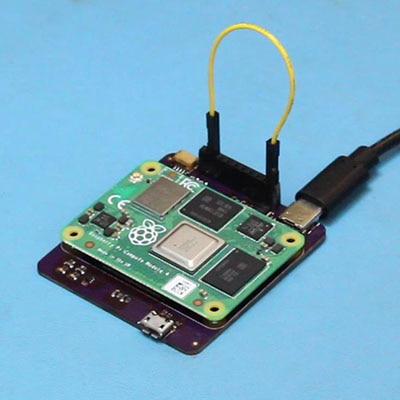
Like the CM4IO board, the schematic is divided up into 2 hierarchical sheets. The first sheet contains a USB-C connector (for power only!), power/activity LEDs, a Qwiic/Stemma connector for I2C breakout boards, and a simple 10-pin GPIO header.
The GPIO header breaks out a UART and SPI bus for connecting to other systems. Additionally, the GPIO header has the nBOOT pin broken out, which needs to be grounded when you are uploading the operating system. Instructions for flashing the eMMC can be found here.
The second sheet contains a single USB micro connector for data. Note that in this particular configuration, the CM4 will act as a client only. You will need to add some additional circuitry (see the CM4IO schematic) if you would like to use OTG or have a multiplexer switch between client (B) and host (A) ports.
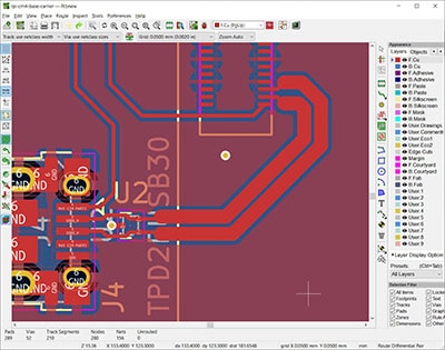
If you switch over to the layout, you can see that I expanded the outline on the sides of the CM4 footprint. Because some of the components (e.g. USB-C connector) are quite tall (over 3mm), you would not be able to fit them under the CM4 module when mounted.
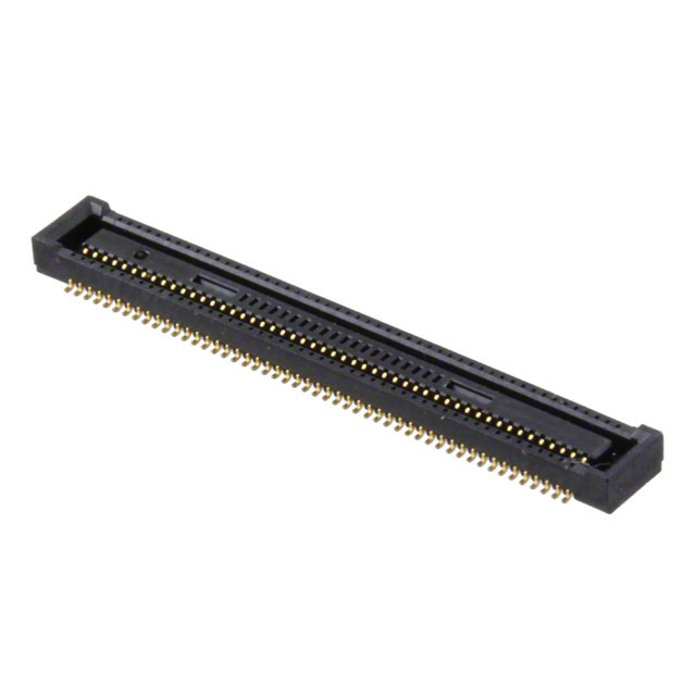
The Hirose headers on the CM4 require a couple of mating Hirose connectors. Here are your two options for mating connectors that you would solder to your board:
https://www.digikey.com/en/products/detail/hirose-electric-co-ltd/DF40C-100DS-0-4V-51/1969476
https://www.digikey.com/en/products/detail/hirose-electric-co-ltd/DF40HC-3-0-100DS-0-4V-51/4282911
The CM4IO board uses the first option, raising the CM4 1.5 mm above the carrier board. You are welcome to use the second option, which raises the CM4 3.0 mm above your board.
However, if you look at images of the CM4 (here), you can see that it contains components mounted to the underside of the board. That means even if you raise the CM4 1.5 mm above your carrier board, you do not have 1.5 mm of space underneath it to add your own components.
As a result, I recommend mounting components outside of the CM4 footprint or on the reverse (bottom) side of the PCB. Note that this would require double-sided assembly (as the Hirose connectors would still need to be on the top side).
To keep with the cheaper single-sided assembly process, I opted to put the components on the carrier board on the sides of the CM4 footprint.
Also note that the USB differential pair data lines were calculated for a 1.6 mm thick, 2-layer PCB. If you use 4 layers or reduce the thickness of the dielectric (e.g. FR4) in your design, you will need to recalculate the size and spacing of the USB lines going to J4. KiCad comes with a great tool (pcb_calculator) to help you do this.
Finally, I decided not to include a microSD card slot on the board to keep things simple. That means you must use a non-Lite version of the CM4. You are welcome to add a microSD card slot (like on the CM4IO board) if you wish!
Please remember that this board is intended to be a demo. Feel free to use it as a place to start for your own Raspberry Pi Compute Module 4 projects!
Resources
CM4IO design files: https://datasheets.raspberrypi.org/cm4io/CM4IO-KiCAD.zip
CM4 Carrier Template: https://github.com/ShawnHymel/rpi-cm4-carrier-template
CM4 Base Carrier: https://github.com/ShawnHymel/rpi-cm4-base-carrier
CM4 datasheet: https://datasheets.raspberrypi.org/cm4/cm4-datasheet.pdf
CM4IO board datasheet: https://datasheets.raspberrypi.org/cm4io/cm4io-datasheet.pdf