The Basics of Stepper Motors
There are several types of electric motors, each with their own advantages and disadvantages. If you’re needing a motor to provide accurate positioning, your options are somewhat limited. You may consider servo motors, which typically only have 180° of rotation. Another option may be some sort of DC motor with feedback via an encoder or even a Hall effect sensor. However, today we’ll evaluate the pros and cons of the almighty hybrid stepper motor and see how it works.
A stepper motor literally takes small steps to advance its rotation. A common configuration for stepper motors is 200 steps per revolution, but you’ll likely see motors with 400 or even more steps per revolution. If you divide 360° by the number of steps per revolution, you’ll find the number of degrees each step will rotate. For example, a 200 step motor will rotate 1.8° per step. Stepper motors may be listed for sale by this figure rather than the number of steps/revolution.
Stepper motors are also able to prevent rotation by holding their position. If you’ve seen stepper motors in action, you may have noticed they can get warm to the touch even while not rotating. This is because the motor is likely being held in position which does consume some power. Being able to hold position and rotate precisely are the two main advantages of stepper motors, which is why they’re found in devices such as CNC machines and 3D printers. Next, let’s take a look inside a stepper motor.
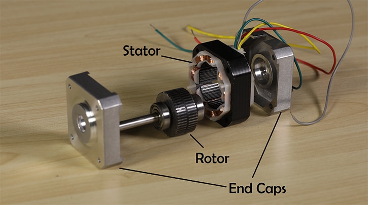
Inside the motor, we’ll see two main components: the rotor and the stator. As you may have guessed, the rotor is the part of the motor that rotates, while the stator is stationary and attached to the motor housing. The rotor assembly consists of a permanent magnet rotor and the motor shaft. Like all magnets, the rotor has a north and south pole. Between these poles the rotor is divided into two halves called rotor cups; on each side of this division there are teeth that alternate. North teeth line up with the troughs between the South teeth.
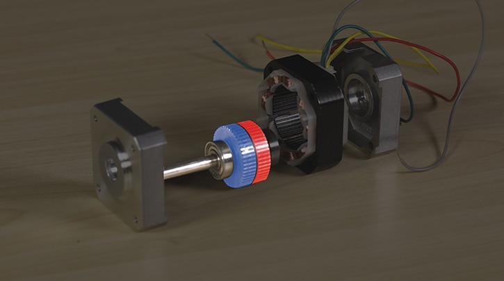

There are teeth in the motor’s stator as well. Looking at the stator more closely, we’ll see that it consists of eight electromagnetic coils. These eight coils are divided between two electrical phases, typically named phase A and B. The image below shows how the phases are divided within the stator. Normally each phase will have two wires exiting the motor, some motors will have an additional center tap wire on each phase.
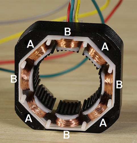
Energizing a phase of the motor will cause the rotor to turn to the next “step”. The teeth of the energized stator poles will attract rotor teeth of opposing polarity. The rotor will be held in this position until power is removed. To rotate the motor continuously, the phases need to be energized in a particular order which is typically +A, +B, -A, -B. It’s impractical to make these changes manually, which is why stepper motors are usually accompanied by a microcontroller and a stepper motor driver IC (integrated circuit) or driver board. Driving a motor in the way described above is called “wave stepping”. There are several different methods of driving stepper motors. Most commonly found are full stepping, which delivers the highest torque, and many degrees of microstepping, which allow for smoother operation.
Stepper motors have revolutionized automation, enabling precision operations even without sensors for feedback. I’ve seen projects such as pen plotters, turntables, parts counters, robotic arms, home CNC machines, solar trackers, and many others. Try one out today and explore the possibilities!
If you’d like to dive further into this topic, check out this eewiki post.

Have questions or comments? Continue the conversation on TechForum, Digi-Key's online community and technical resource.
Visit TechForum


