Accelerate the Design of Precision Vibration and Sound Sensing Systems Using Proven Circuits and Components
I'm amazed at how much time we spend perfecting medium-bandwidth precision analog circuits. Each circuit design problem seems like it requires a considerable amount of start-up time to get the basic configuration going. These systems include vibration, sound, data acquisition (DAQ), position rotation, and sonar. Despite the various sensing options, there has to be an easier way to approach these designs to save time.
For sure, they all have different input sensors, requiring other excitation circuits. But looking past that, they have analog gain configurations and analog-to-digital converters (ADCs) to finally get the finished signal across an isolation barrier. What’s more, is that all these systems operate in the medium bandwidth of DC to 500 kilohertz (kHz). Is this enough commonality to define a virtual, usable circuit for all systems?
Well, let's look at a basic design for these systems for commonality in the circuit and cross-reference this to what’s available on Analog Devices’ Precision Medium Bandwidth page. There is a circuit class that quickly tackles measurements from vibration, sound, DAQ, position rotation, and sonar systems. These precision, medium-bandwidth, signal-chain sensor circuits fall into signal bandwidths ranging from direct current (DC) to 500 kilohertz (kHz), with ADC speeds up to 4 mega samples per second (MSPS) (Figure 1).
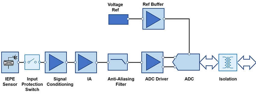 Figure 1 : The fundamental medium-bandwidth sensing circuit starts with analog signal refinement and gain components, followed by the ADC drive circuit and the ADC. (Image source: Bonnie Baker)
The Figure 1 circuit should be familiar to most analog designers. The sensor and signal conditioning block start at the input on the left. This signal chain uses high-quality digital data from highly sensitive integrated electronics piezoelectric (IEPE) sensors. The IEPE is a piezoelectric sensor with built-in impedance conversion circuits that can measure vibration, sound, acceleration, force, or pressure.
The signal conditioning block can be a light-to-voltage converter, such as a transimpedance amplifier (TIA), or another signal-massaging circuit. The purpose of the instrumentation amplifier (IA) block is to configure a one-time gain so that the signal meets the ADC’s input range.
The anti-aliasing low-pass filter is a curious animal and absolutely must exist in the analog, not the digital domain. Depending on the circuit’s noise and the type of ADC, this filter can range from a resistor/capacitor first order, up to a 5th-order dual amplifier low-pass filter with surrounding resistors and capacitors. But in all cases, the low-pass filter’s cut-off frequency reduces aliasing errors by being equal to or below the Nyquist frequency.
The ADC driver is a critical part of this circuit, providing ample current charge for the ADC's input capacitive switching network while maintaining signal stability. Now, moving on, a typical ADC in this circuit is the successive approximation register (SAR) ADC or a sigma-delta (Σ∆) converter. The maximum resolution of the SAR-ADC is 18 bits, but the actual number of dependable bits (#bits) with a signal-to-noise ratio (SNR) of 100 decibels (dB) is 16.3 bits. To calculate the number of dependable bits using the ADC’s SNR value, use Equation 1:

Where # bits = dependable rms actual bits
SNR = the ADC’s signal-to-noise ratio (SNR)
Equation 2 finishes this series of equations by determining the actual ADC’s rms resolution.

Where RESrms = actual rms resolution
Surprisingly, the actual rms resolution (RESrms) of the Analog Devices 18-bit AD4003 SAR-ADC, with an SNR of 100.5 dB, is 16-bits rms.
Vibration and sound systems
The next set of medium-bandwidth circuits takes advantage of digital control components, replacing the IA with a programmable gain (PGIA) version and the SAR-ADC with a 24-bit sigma-delta (Σ∆) ADC. The combination of the PGIA and the 24-bit Σ∆ ADC allows the microcontroller or microprocessor to implement analog gain and bandwidth digitally.
Vibration and sound signal chains use low-noise and wide-bandwidth devices to implement edge node sensing and high-performance vibration and sound DAQ channels. Some vibration and sound signal chains include devices with integrated digital filters to simplify analog filter design, reduce interface speed, and reduce power consumption in the digital host.
Edge node vibration sensing
The signal chain devices in Figure 2 contain features such as:
- Enhanced digital functions
- A wide bandwidth compact solution
- Three-axis sensing
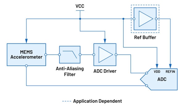 Figure 2 : A vibration measurement circuit with enhanced digital functions, a wide bandwidth compact solution, and three-axis sensing. (Image source: Analog Devices)
Enhanced digital functions: The 24-bit Σ∆ ADC is the AD7768-1, which has a Sinc filter with a bandwidth of DC to 204 kHz, and a low-ripple finite input response (FIR) filter with a bandwidth of DC to 110.8 kHz. Its typical dynamic range is 108.5 dB, equivalent to 17.73-bits rms. The programmability of this device includes the output data rate (ODR), filter type, and latency. The ODR values are up to 1024 kilo samples per second (kSPS).
The integrated digital filter simplifies analog filter design, reduces interface speed, and reduces power consumption in the digital host.
Wide bandwidth compact solution: Figure 2 shows another edge noise vibration sensing circuit that is a simple, highly compact solution with a low component count. This circuit is easy to use with its analog-front-end (AFE) and low dropout (LDO) regulator integration. Additionally, the power consumption of the circuit is very low.
The 16-bit, 1 MSPS, ADAQ7988 μModule DAQ system combines the functions of the ADC driver and SAR ADC. The Analog Devices ADXL1004 microelectromechanical system (MEMS) is a low-noise, x-axis ±500 g, 10 kHz accelerometer.
Three-axis sensing: This vibration system utilizes a three-axis simultaneous sampling algorithm to measure vibration. The integrated digital filter in the four-channel (Analog Devices AD7768-4), 24-bit, simultaneous sampling Σ∆ ADC simplifies the analog filter design, reduces interface speed, and reduces the power consumption of the digital host.
Vibration sensing DAQ module
The systems in Figure 3 that have vibration sensing DAQ modules are the:
- IEPE unipolar input
- IEPE bipolar input
Both systems utilize a high-performance DAQ signal chain with wide bandwidth and low noise.
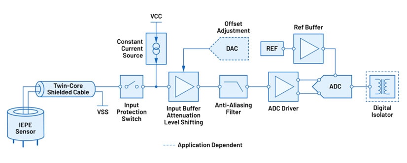 Figure 3 : The systems with vibration sensing DAQ modules are the IEPE unipolar input and the IEPE bipolar input: both require a high-performance DAQ signal chain with wide bandwidth and low noise. (Image source: Analog Devices)
IEPE unipolar input: For this configuration, the input is unipolar from the IEPE through the input buffer, anti-aliasing filter, and into the ADC driver. There is excellent AC and DC performance because of the inclusion of a precision amplifier, Analog Devices’ AD8605. The AD8605 offers excellent offset voltage (65 microvolts (µV)), low noise (8 nanovolts-per-root Hertz (nV/√Hz)), and low input bias current (1 picoampere (pA)), enhancing the support of very-low-frequency sensing.
On the digital side, the IEPE unipolar input circuit uses the ADA4945-1 ADC driver and the 24-bit Σ∆ ADC, the AD7768-1.
IEPE bipolar input: In this circuit, the bipolar signal input provides a wide common-mode range. This system is suitable for long cable connections to the sensor. There is a direct interface with IEPE sensors, and the digital isolator makes this system ideal for channel-isolated systems.
This system does not need the offset digital-to-analog converter (DAC), but the digital isolator (Analog Devices’ ADuM141D) makes it easier to repurpose the circuit for a general purpose DAQ instrument.
Conclusion
With sensors being widely deployed, designers are working to use existing designs to save time and resources. Using Analog Devices’ analog precision medium-bandwidth circuits and components accelerate the implementation of leading-edge vibration and sound sensing systems.

Have questions or comments? Continue the conversation on TechForum, Digi-Key's online community and technical resource.
Visit TechForum


