Using Efficient SPI Peripherals for Low-Cost MCU-Based IoT Designs
投稿人:电子产品
2015-07-22
Efficient Internet of Things (IoT) designs must balance a host of requirements that often work against each other. Low cost is important, but often supporting all the key features required by the application increases MCU pin count and memory size—two things that work against low cost. Low power is also important for IoT applications where battery operation is a must. Adding features and improving performance can up the power requirement, however. Clearly finding the right balance between all these requirements can be a problem, but that’s just the type of challenge engineers expect from cutting-edge designs.
One of the most effective ways to cut this design Gordian knot is to look for system architecture changes that can frame the problem differently. Using serial interfaces efficiently, for example, can cut the number of pins required by the MCU and help optimize board space, power, and performance. The efficient use of MCU SPI peripherals can do just that. This article will show some illustrative IoT application examples where SPI-style peripherals provide new architectural options that dramatically improve efficiency.
SPI connectivity in cost-oriented embedded designs
One of the most difficult tasks when designing cost-oriented systems is to balance functionality and cost. In MCU-based designs, this conundrum can often manifest itself in the need to add extra pins to the MCU so that additional peripherals can be added to the system. The extra functionality the peripherals provide are important differentiators that, hopefully, make the design more valuable to the user than a design that uses just the standard MCU. After all, the MCU with no external peripherals can be very difficult to differentiate from another MCU-based design.
And while it is true that in many MCU-based designs it’s the software that differentiates one design from another, it’s often the case that an innovative combination of software and external hardware is much more compelling. This can be even more important in cost-oriented designs where increasing the value to the user is more important than just keeping the cost low. In the fast growing and competitive IoT market finding the right value will be critical to product success.
When balancing additional features with low cost one of the most common architectural approaches is to use low-pin-count serial interface standards to connect MCUs to external peripherals. When multiple peripherals can share the same low-pin-count interface, it can dramatically reduce the number of pins required by the MCU, which allows low-cost, low-pin-count MCUs to be used. Low-pin-count peripherals are typically less expensive than their high-pin-count cousins, so this can further reduce system cost. Smaller pin counts can reduce board space, and also reduce the number of traces required. This reduces manufacturing complexity, since fewer signal layers are required on the printed circuit board.
One of the most popular serial interfaces is the Serial-Peripheral-Interface (SPI) standard which evolved to simplify the interconnection of peripherals to MCUs. As shown in Figure 1, the interface requires only four signals at the peripheral-the serial-clock input (SCLK), the master output slave input (MOSI), the master input slave output (MISO), and the slave select (SSn). These four signals are sufficient to support a bus with several peripherals all connected to the host controller. The host communicates with the selected peripheral and either transmits data or receives data over the MOSI or MISO signals. Transfer lengths are from 8 to 16 bits with transfer speeds that depend on the implementation, but can often provide bit rates from 10 to 100 Mbps. SPI is usually found on peripherals with low-bandwidth requirements like sensors, Flash memories, and analog-to-digital converters.

Figure 1: SPI controller and peripherals minimize interconnect. (Courtesy of Wavefront Marketing)
For more information on the SPI standard DigiKey has several Product Training Modules that discuss the SPI standard and various devices that support SPI implementations. The interested reader can use these to dig deeper into the details of the SPI standard.
MCU SPI-peripheral control
Most modern MCUs have SPI-controller peripherals that easily and efficiently manage multiple SPI buses. Controllers can usually be configured as either the host or as a peripheral and it’s not unusual for an MCU to act as both a host and a peripheral. For example, in chassis-management applications the MCU can be a host to the various sensors within the chassis while also acting as a peripheral to the main chassis controller processor, often using MCUs as distribute aggregators of remote sensors to offload significant “low-level” processing from the main CPU. This can improve processing efficiency for the main CPU and reduce power for the overall control subsystem. Figure 2 shows the block diagram of the SPI controller for the NXP LPC1756F MCU and it illustrates the main elements of most SPI controllers.

Figure 2: NXP LPC1756 MCU SPI Controller Block Diagram (Courtesy of NXP)
The shift-register block is used to communicate with the various SPI peripherals on the bus, either in host or peripheral mode. The clock generator and detector source the clock in host mode and receive the clock in peripheral mode. The output enable logic is used to determine the direction of the signals on the SPI bus, depending on the operation mode. The SPI-register interface provides access to the configuration and data registers within the peripheral. Finally, the state-control block manages all the SPI operations of the peripheral.
The NXP LPC1756F MCU also has another SPI-controller peripheral, SPI0/1 that in addition to SPI also supports the 4-wire and MICROWIRE interfaces. It also includes FIFO buffers and can be accessed via DMA. When provided with multiple SPI options, make sure you match the SPI-peripheral controller with the needs of the external device. For example, sensors may not need DMA but an external memory could benefit greatly from a DMA capability within the SPI controller.
SPI-controller hardware is only one piece of an SPI solution. It is also useful to review the software capabilities that come along with the controller. Often the supporting software is best demonstrated with an evaluation or development kit. For example, the Renesas RX600 Demonstration Kit includes drivers and sample code that can be used to evaluate the ease at which a target SPI-peripheral controller can be implemented. The board includes an SPI Flash and SPI EEPROM so drivers and example code are available to simplify implementation. The kit also features a touchscreen LCD so if the target application uses the memory for a graphic-user interface, much of that code can be used as well. Keep in mind your target application and how the SPI bus is to be used so you can leverage as much of the code available from a development kit as possible.
SPI memory
On of the downsides of using a small inexpensive MCU is that there may not be enough on-chip memory for the application. Instead of using a larger, more expensive MCU it may turn out to be more cost effective to use an external memory. In fact, since external memories can typically provide significantly more storage than that provided by high capacity MCUs, it is much easier to differentiate a design that uses external memory from one that uses on-chip memory. With enough storage user interfaces can be more intuitive, local data can be more easily stored until it is more energy efficient to transfer the data, video and audio are much easier to support, and user functions with more intelligence can be supported. If you are looking for ways to add value to your design, external memory is an excellent option.
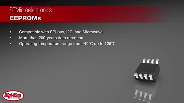
By using modern flash memories that feature an SPI bus, external capacity can be added without the need for a multitude of MCU pins. This can keep cost down and can simplify the software needed to access external memory. For example, the STMicroelectronics M95xxx EEPROM is available with the SPI bus in a small 8 SOIC package. Similar devices are available with other serial interfaces as shown in Figure 3. The MICROWIRE and I2C style interfaces use either 2 or 4 wires, so they could be appropriate for reducing MCU pin count, but note the difference in clock rate: the SPI version can operate 10 to 20 times as fast as the other two devices. This is one of the reasons that SPI tends to be more popular, it can support higher clock rates so the application can transfer data quickly and usually more power efficiently as well. (The quicker you can transfer data, the less time the device needs to be powered up.)

Figure 3: Characteristics of STMicroelectronics Serial Interface EEPROMs- M24C/M95/M93C. (Courtesy of STMicroelectronics)
SPI-bus-memory devices using flash technology are available as well. For example, the Micron Technology M25P05 is a 512-Kbit SPI NOR flash memory with a 50 MHz clock rate. Data can be programmed from 1 to 256 bytes at a time making it very useful in sensor and logging applications where small amounts of write operations are the norm. It has a deep power-down mode of 1 μA and is available in a variety of small low-pin-count packages such as SO8, VFQFPN8, TSSOP8, and UFDFPN8. A write-protect feature allows part of the memory to be configured as read-only and an additional write-protect signal supports an additional hardware protection mode to protect data from corruption in overly noisy environments. Low power and robust data protection are very useful in Industrial IoT (IIoT) applications where remote energy harvesting sensors are often placed in noisy environments.
Small specialized memories are also available as SPI peripherals. For example, Microchip Technology provides small SPI memories for storing Ethernet MAC addresses. The Microchip 25AA02E is a 2-Kbit EEPROM that can be used pre-programmed with a globally unique 48-bit or 64-bit node address that is compatible with EUI-48 and EUI-64. Available at a low price in a small 8-bit SOIC and consuming only 1 μA in standby mode, it is easy to add to an embedded application that requires Ethernet connectivity on a budget.
SPI peripherals
A wide range of peripheral functions for sensing and monitoring are now available for the SPI bus. Perhaps the most universal peripheral in MCU applications is an analog-to-digital converter (ADC). Often analog sensor outputs need to be converted to digital, and if the on-chip ADC does not provide the functionality required, an external ADC may be needed. Additionally, if many ADC inputs are required it may be more cost effective to use an external device, with many inputs, to keep the MCU pin count low. For example, the Analog Devices AD7298BC SPI-compatible ADC has 12-bits of resolution, 8 inputs, an on-chip temperature sensor, and fast throughput of 1 MSPS. An on-chip channel sequencer makes it easy to monitor several inputs, with a pre-programmed sequence, to simplify channel management. With a power-down current of less than 10 μA and availability in a small 20-lead LFCSP, it is a good fit for small-board-space, low-power applications.
In IoT applications, accelerometer and gyroscopic sensors can be useful in tracking, orientation, safety, and positioning functions. Often these types of sensors can be found in combination to simplify implementation. Additionally, when multiple sensors are tightly coupled with the local MCU, readings from multiple sensors can be combined to create more intelligent functions. For example, if allowable windows for acceleration and orientation are defined, the MCU can compare readings to the window settings and need not generate an alert unless the readings are outside the acceptable boundary. This minimizes overhead for the management CPU, typically a much more power-hungry device than the MCU. The STMicroelectronics LSM6DS0TR includes a 3D accelerometer and a 3D gyroscopic sensor on a single chip. Both sensors can be used simultaneously or the gyroscope can be powered down while the accelerometer is active. The SPI bus is used to configure and obtain readings and keeps the pin count small so it can be used in an LGA-16L package. A block diagram of the device (Figure 4) shows the accelerometer in the upper section and the gyroscope in the lower section. The SPI bus is shown on the bottom right of the diagram.

Figure 4: Block Diagram of STMicroelectronics SPI Accelerometer and Gyroscopic Sensor (Courtesy of STMicroelectronics)
One of the most important features of the device is the data register FIFO. The FIFO provides 32 slots of 16-bit data for each of the gyroscope’s three output channels—pitch, yaw, and roll. It also provides a 16-bit data FIFO for each of the three accelerometer output channels, X, Y, and Z. This allows consistent power saving for the system, since the MCU need not continuously poll data from the sensor, but it can wake up only when needed and quickly burst the data out from the FIFO.
Another popular sensor in MCU-based designs is the Hall-Effect sensor. This sensor is often used in positioning systems where the angular position, rotational speed, and direction of an object are important. The Hall-Effect allows contactless sensing using the current generated by a magnetic field. Some Hall-Effect devices use a Circular Vertical Hall (CVH) technology to simplify integration of the sensing and supporting digital circuitry. For example, the Allegro Microsystems A1334 Hall-Effect 360 degree angle sensor uses an on-chip CVH sensor along with an analog front end, EEPROM-based programmable calibration parameters, and digital-signal processing techniques to simplify sensor use. An SPI bus makes it easy to connect the sensor to an MCU. The device has a maximum VCC of 26.5 V so it can be used in automotive battery-powered applications for steering and motor control. Make sure your sensors support any harsh environmental conditions your application may have to avoid reduced product lifetime or high-failure rates.
Conclusion
The efficient use of SPI-style peripherals can help optimize device cost, board space, power, and performance for IoT applications by providing the savvy designer with additional architectural options. By efficiently using SPI peripherals and on-chip MCU SPI controllers, designers can often find an optimal mix for feature-rich, low-cost implementations.
For more information about the parts discussed in this article, use the links provided to access product pages on the DigiKey website.
免责声明:各个作者和/或论坛参与者在本网站发表的观点、看法和意见不代表 DigiKey 的观点、看法和意见,也不代表 DigiKey 官方政策。