Liquid Level Sensing is Key Technology for Today’s Systems – Part 1
投稿人:电子产品
2011-09-22
We don’t think about it much, but technologies that can sense fluid or liquid levels are integral to many of the business and household items we use every day; the drinking water that comes from the tap, the oil level in a car, or the color coming out of a print cartridge. The ability to sense fluid levels is key to making these the reliable and safe technologies and systems we depend on.
In some cases, mechanical solutions are sufficient. For example, a toilet float valve is suitable for shutting off water flow at a determined level. But what if it could detect a fault, send an alert signal to a central monitor and eliminate a costly flood by automatically shutting down the input water supply?
In today’s increasingly resource- and energy-conscious world, mechanical systems are giving way to more sophisticated electronic and electromechanical approaches that add layers of functionality and integration as part of a more comprehensive system. Here, analog, digital and mixed-signal approaches, particularly with embedded microcontrollers, can do a better job, making possible feats that mechanical systems can’t reasonably be expected to handle.
This article is the first of two and describes techniques and devices that can be used to monitor liquid levels. It also discusses the limit detect devices, resistive and capacitive sensing techniques. The subsequent article will discuss sonic, optical and gravitational techniques.
Level playing field
The simplest type of liquid-level monitoring is a limit detector. Typically implemented as float switches, these detectors trip a mechanical or sensor-based switch when a pre-determined level has been reached. In hermetically sealed geometries, the float mechanisms come in a variety of materials suitable for different types of caustic and noncaustic liquids.
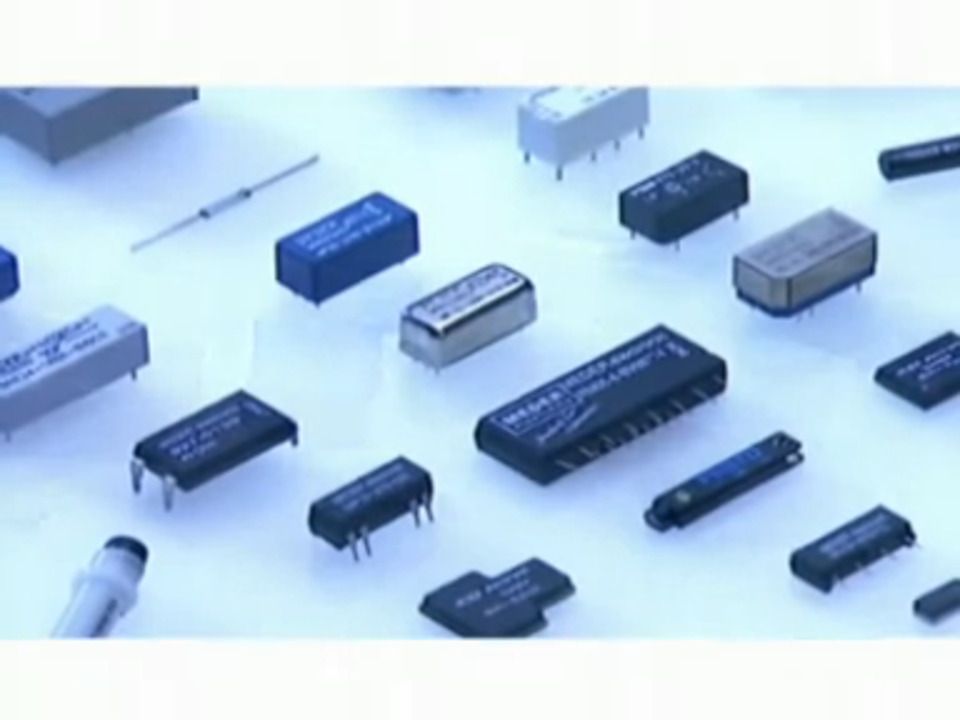
The Meder LS01-1B66-PA-500W, as seen in Figure 1, is well suited to detect the fill level of a petroleum-based tank. Its magnetic float configuration with a polyamide stem and float materials make it an intrinsically safe way to detect harmful liquids such as gasoline.
 Figure 1: The Meder LS01 series is a magnetically triggered float switch capable of switching up to 100 W in water or petroleum tanks.
The electronic approach
Fluid levels can also be measured using electronic techniques. These include resistive, capacitive, optical, sonic and gravity.
Resistive is the simplest technique and is reliable when using a consistent liquid with a relatively small variation of resistance. With this approach, electronics can more easily deal with the replication of individual sensors to provide level information and limits, as illustrated in Figure 2.
 Figure 2: Many resolution steps can be implemented using a resistive threshold technique.
The sensor points can be inserted directly into the tank. Terminal posts on the other side can wire directly to the interface board, but most designers prefer a sensor board that can be inserted and removed in a single location. The fewer holes drilled into a tank, the fewer possible sources of leak and failure.
Because the resistance of the fluid is known, a voltage drop across a series resistance will change drastically from virtually an open circuit to a DC level when liquid touches the probe point. Since each additional sensor increases the effective resolution, this technique can be used to achieve a high level of resolution. For example, 16 sensors are more than adequate to monitor water levels in an RV water tank.
The simplest use of op amps in this case can create a nice bar-graph-style display corresponding to the liquid level, which is shown in Figure 3. A general-purpose part like the National Semiconductor LM324 is a good candidate and will drive the LEDs directly.
 Figure 3: Replicating the same stage will provide as much resolution as needed. The LEDs can be replaced or paralleled with optoisolators to drive logic signals with high isolation.
The voltages used should not cause electrolysis in the tank. It’s important not to build up explosive gasses. One technique is to sense every so often rather than in real time. This ensures that power is off to the entire array for most of the time, only powered up when needed for a quick measurement. Also, shunting each side of the sensor to ground when not in use will not let a charge build up.
Capacitive sensing
Like resistive, a capacitive type of sensor can be an array of sensors that creates a piecewise linear step detector. But capacitive sensing techniques can also operate as a pure linear function. This means a single sensor can sense empty, full or anywhere in between.
The capacitive sensor creates or changes a time constant that controls an oscillator or pulse generator. Because current can be controlled or fixed at a set limit, the frequency of an oscillator directly reflects the relative level of the liquid.
A simple strip sensor in 2D shows how this works in Figure 4. When there is no fluid, there is virtually no capacitance. A baseline capacitor in parallel with the probe sensor will cause an oscillator to oscillate at the highest frequency.
 Figure 4: The capacitive sensor will exhibit a lower frequency when liquid levels are higher. A parallel capacitor can set the open-circuit oscillator base frequency.
Since capacitance is directly proportional to surface area, a concentric tube arrangement gives higher working capacitance ranges than a strip sensor that just has two conductive paths, as seen in Figure 5.
 Figure 5: The tube within a tube cap sensor maximizes surface area and can be made to any length making it an ideal topology for small or large tanks.
 Figure 6: A typical oscillator can be made using a 555 timer. The frequency of the oscillator indicates the liquid level.
免责声明:各个作者和/或论坛参与者在本网站发表的观点、看法和意见不代表 DigiKey 的观点、看法和意见,也不代表 DigiKey 官方政策。