Selecting A Fan
2015-07-22
Designing a forced convection cooling system for a chassis or cabinet can be a complicated task. However, it must be done correctly to ensure the performance and reliability of the enclosed electronics. Many different thermal, mechanical and electrical effects must be considered for the successful design of such cooling systems1.
The first step is to determine the type of fan that’s needed. This will be based mainly on the chassis design and the allowable space.
There are two major fan types:
1. Vane-Axial Fans – Air flow is parallel to the fan’s axis. It provides a high air flow rate with low pressure (Figure 1).
2. Blower Fans – Air flow from this fan type is perpendicular to its axis. The air flow rate is low and there is high pressure (Figures 2-4).

Figure 1: Sanyo Denki vane-axial fan.

Figure 2: Sanyo Denki blower fan.

Figure 3: Eucania tangenial blowers.

Figure 4: Eucania intergrated blower.
To select the appropriate fan, we must estimate the system’s air flow requirements. For low power, uniform heat loads we can use a simple, steady-state analysis to balance air flow and temperature rise.
The power dissipation of the chassis, and the desired temperature rise, are used in the following equation to obtain a target flow rate2:
![]()
Where:
Q = heat dissipated in enclosure
ṁ = mass flow rate through enclosure
CP = specific heat of air
ΔT = target temperature rises from intake to exhaust
For high thermal loads with concentrated heat sources, one must design to the worst case component temperature. Spot cooling may be accomplished with internal fans, heatsinks, ducting, and other methods.
Next, the total system thermal impedance curve is needed, or at the very least, you should know the system pressure drop at the desired flow rate.
System resistance is defined as:
![]()
Where:
P = system pressure
K = load factor (system dependent)
ρ = air density
Q = air flow rate
n = air flow quality constant; varies between 1 (laminar) and 2 (turbulent)
For practical purposes, the value of K can only be found experimentally or by using computational fluid dynamics. Due to the complex nature of today’s electronic enclosures, an accurate value for K cannot be derived analytically. In a modern enclosure, the air flow is mixed (laminar, turbulent, pulsetile, etc.) and the value of n can be conservatively chosen as 2.
The calculated flow rate at a specific static pressure can be compared to a specific fan curve. This will determine if the fan will be adequate. An example of a fan curve is shown in Figure 5. Point A is known as the “no flow” point of the curve, where the fan is producing the highest pressure possible. Next is the stall region of the fan, B, which is an unstable operating area and should be avoided. The region from point C to D is the low pressure area of the fan curve. This is a stable region of fan operation and should be the design goal. It is best to select a fan that performs to the higher flow area of this region to improve fan efficiency and compensate for filter clogging.

Figure 5: Typical fan and impedance curves3.
In many systems, a single fan cannot deliver the full volumetric flow rate needed. In these situations multiple fans can be used, configured either in parallel or in series. In order to determine which configuration is more appropriate, the system impedance curve is needed once again (Figure 6). For a high impedance system, two fans in series will produce a higher flow rate than they will in parallel. The opposite behavior can be expected in a low impedance system, where parallel fans are preferred.
An important step to be addressed once the fans have been selected is to configure them in a blow-through or pull-through arrangement. The air flow into a fan can roughly be modeled as laminar, whereas the exit air flow is highly mixed. This phenomenon can be useful in thermal management. An example of this is seen inside a typical telecom sub-rack. Due to the varied resistance that the PCBs impose, and the close proximity of the fans (fan tray) to the cards, the conditioned flow will help provide better velocity distribution in the sub-rack, which also functions as a plenum.

Figure 6: The effect of multiple fans on system pressure and flow rate4.
In the blow-through configuration, the turbulent air has a positive effect on the heat transfer coefficient. This can be useful when dealing with concentrated heat sources. The blow-through design allows the fan to push cooler air, which improves its pressure capability and extends the life of the fan. In this arrangement the enclosure is slightly pressurized. This prevents unfiltered air from being drawn through the joints and gaps in the chassis.
Common Fan Laws
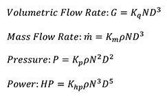
Where:
K = constant for geometrically and dynamically similar operation
G = volumetric flow rate
N = fan speed in RPM
HP = power output
ṁ = mass flow rate
D = fan diameter
ρ = air density
This article first appeared in the Qpedia Thermal eNewsletter in March, 2007.
References:
- Ellison, G., Fan Cooled Enclosure Analysis Using a First Order Method, Electronics Cooling, October 1995.
- Turner, M., All You Need to Know About Fans, Electronics Cooling, May 1996.
- Daly, B., Woods Practical Guide to Fan Engineering, Woods of Colchester, Ltd, 1992.
- Comair Rotron, Establishing Cooling Requirements: Air Flow vs Pressure, March 12, 2007.
免责声明:各个作者和/或论坛参与者在本网站发表的观点、看法和意见不代表 DigiKey 的观点、看法和意见,也不代表 DigiKey 官方政策。


