Power over Ethernet: The Ideal Infrastructure for Networked Lighting?
投稿人:DigiKey 欧洲编辑
2016-05-17
The debate is closed: LEDs are the future of lighting. Discussion has moved on to issues such as finding the best and most efficient means of powering LED-based luminaires.
LED replacement lamps in the standard form factors established during the incandescent era provide a drop-in upgrade option that can be powered directly from the legacy supply, which is typically a high-voltage AC line. Such a straightforward swap, however, does not exploit the full potential of solid-state lighting technology to deliver greater energy efficiency, user comfort, convenience and other value-added features than have ever previously been imagined.
LEDs can be readily paired with sensors, wireless communication modules, and embedded processors, allowing LED light fixtures to become smart networked sensor hubs. Connecting such smart hubs to the local area network (LAN) delivers valuable future-proofing by enabling the system to take advantage of emerging capabilities on the IoT (Internet of Things) without an expensive lighting replacement (Figure 1).

Figure 1: LAN connectivity can realize the full potential of smart LED-lighting hubs.
The question remains, how to supply power to the luminaire.
DC power distribution has cost and efficiency advantages that result from eliminating the need to convert high-voltage AC to a lower DC voltage suitable for powering the LEDs. In particular, Power over Ethernet (PoE) provides an especially convenient means of distributing DC power over the same network cable that carries sense and control signaling. In this way the smart LED hub can be powered, connected and controlled over the LAN, with no need for separate power cabling. Ordinary network cable can be used, which is both inexpensive and easy to install without requiring the services of a qualified electrician. The network can also be adapted easily in response to changing requirements, by adjusting access ports accordingly.
In addition, PoE enables better overall network power management. It provides discrete control over the power of the connected devices and, with suitable battery backup or emergency power generation connected to the network, can provide continuous lighting during a power outage. This can relieve the need for a specialized secondary emergency lighting system, and also creates the opportunity to communicate changing situations to building occupants, such as indicating a safe exit or changing color at the command of the controller to indicate areas of the building to avoid.
Recap on PoE Technology
PoE technology is regulated by the IEEE 802.3 standard, which supports 10BASE-T, 100BASETX, and 1000BASE-T networks. The standard was originally released in 2003 and updated in 2009. IEEE 802.3 specifies that power is supplied via Power-Sourcing Equipment (PSE) located in the switch/hub, and also allows a PSE to be used in a midspan to insert power in the network. This approach supports legacy networks and offers more control over which network segments are powered. The connected device receiving the power is commonly referred to as a Powered Device (PD). To support legacy installations, the PSE can supply power over two pairs of wires, at a maximum of 15.4 W over a voltage range of 44 VDC to 57 VDC using cat. 3 or better cabling. In an endpoint implementation, as shown in Figure 2, the PSE uses pairs 1-2 and 3-6 for power distribution.

Figure 2: PSE and PD connections in a PoE endpoint implementation.
The PoE standard also specifies that the PSE can supply 30 W (over two pairs) or 60 W (over four pairs) over a 50 VDC to 57 VDC voltage range using cat. 5 or better cabling. For these three power scenarios, the PD is limited to a maximum power draw of 13.0 W, 25.5 W, or 51 W, respectively all over a 37 VDC to 57 VDC voltage range. The maximum allowed power draw is lower than the supplied power to account for worst-case power loss in the cable.
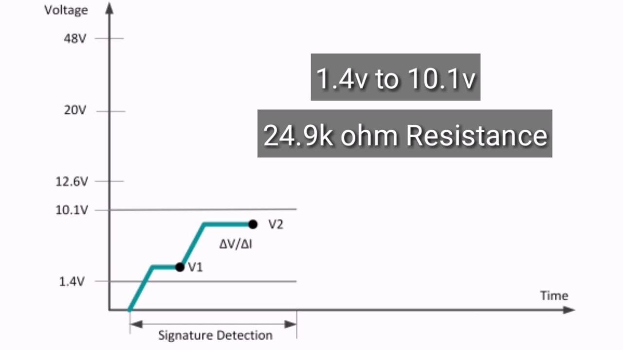
The PD negotiates a power class with the PSE during its initial connection. All PDs include a 25 kΩ resistor across powered pairs, to allow the PSE to detect when a PD connects and disconnects from the network. PoE does not degrade data communication performance. In fact, it protects the network equipment from overload through negotiation of power consumption between the PoE unit and the connected devices. Power is only delivered to compatible devices and is blocked to incompatible legacy devices. This approach allows users to freely and safely mix legacy and PoE-compatible devices on their network.
Network for Smarter Lighting
In a PoE configuration, each LED fixture can be a standard RJ45 connector plug-and-play device with its own IP address that is individually addressable. Connecting smart LED hubs via PoE provides power for each LED hub to emit light. The PoE connection also enables each LED hub to collect information from its various sensors and communicate the data back to a controller (Figure 3).

Figure 3: Smart, connected LED lighting can save energy and improve comfort and productivity.
The collected information could include ambient light intensity, temperature, humidity, and proximity/room-occupancy detection. For example, occupancy sensors can be used to ensure that lighting is activated only upon someone's entrance into a space. When the sensors no longer detect the presence of anyone, lighting is automatically turned off. Ambient light sensors enable daylight harvesting because the LED lighting is automatically adjusted to maintain lighting when not enough sunlight is present.

Figure 4: Programming the Si1141 in autonomous-sensing mode.
Operating over PoE, the LED lighting system becomes an information network that enables users to control the lighting and temperature in their immediate vicinity. The system can access other building services (for example, with a smartphone) like proximity sensors to discover the closest available meeting room. It can also let facility managers better measure, monitor, and control other building systems such as heating and ventilation in real time. With facility managers now doing historical trend analysis on this data, they could identify opportunities for improved energy and operational efficiency. These opportunities for efficiency include adjusting temperature, lighting, and cleaning schedules based on how users actually behave.
A PoE LED network provides additional benefits of future proofing, because the integrated smart sensor hubs are already positioned where people will gather. If a facility manager wants to add new sensor or communication modules, such as distributed short-range wireless access points, it can be accomplished at low margin cost because the power and data are already wired to the most useful locations.
PoE-Ready LED Lamps
Maxim LED drivers such as the MAX16832 have a wide input-voltage range of 6.5 V to 65 V, which allows direct connection to the 50-57 V PoE supply voltage. By also providing maximum output current of 1 A, this device is ideal for supporting PoE applications. The driver supports both analog and PWM control to enable flicker-free dimming. Many of the external components usually required in a controller, such as the power MOSFET, are integrated in the MAX16832.
Creating a smart PoE-powered LED hub requires a number of other components, in addition to the MAX16832. Maxim has created a reference design for a PoE-powered LED hub, in which the MAX16832 is powered directly by a MAX5969 PD controller. This controller also supplies a MAX15062 DC/DC converter used to power a small host microcontroller. The MAX15062 accepts an input voltage of up to 60 V, and delivers up to 300 mA at 3.3 V, 5 V or variable voltage depending on the exact device specified. Its footprint of 2 mm x 2 mm in the 8-pin TDFN package makes this one of the industry's smallest high-voltage synchronous buck regulators, and ideal for the space-constrained environment of a smart LED lighting hub.
The reference design also makes provision for adding an HM-12 or BL-600 Bluetooth® module, or ESP8266 Wi-Fi module, as shown in Figure 5. This enables the user to control the lighting, including on/off or dimming levels, using an Android or iOS Bluetooth controller app.

Figure 5: Maxim's PoE-ready smart-lighting reference design.
The MAX16832C evaluation kit is a fully assembled and tested board that simplifies setting up digital PWM dimming using the MAX16832 IC. The board requires an external power supply of between 6.5 V and 65 V, and delivers an output voltage of up to 64 V to drive a user-supplied LED string at 666 mA. The board is designed for optimum thermal dissipation, and also features a thermal-foldback and temperature-simulation circuit.
Summary
PoE enables LED lighting networks to use a power supply that is easier and less expensive to install, maintain, and modify than legacy power infrastructures. PoE-powered LED lighting networks provide facility managers and building owners with an unprecedented ability to dynamically monitor and control each individual LED lamp. Because PoE-powered LED lighting networks can easily integrate with other components, such as sensors and wireless communication modules, they provide future-proofing and are more easily able to support the emerging capabilities becoming available in IoT implementations. A rich selection of reference designs and development resources is available to help simplify and accelerate the design of PoE-powered smart lighting/sensor hubs.
免责声明:各个作者和/或论坛参与者在本网站发表的观点、看法和意见不代表 DigiKey 的观点、看法和意见,也不代表 DigiKey 官方政策。