How to Get Better Measurements, Faster, and Accelerate Product Development

作者:Jeff Shepard

投稿人:DigiKey 北美编辑

Developing advanced electronic and electromechanical products can be a race against time. Powerful new data acquisition (DAQ) tools can help simplify and accelerate the development process and win the race.

Those DAQ tools deliver high performance like 20-bit, ±10 V inputs for sensors, batteries, and other devices at up to 1 MS/s/ch sample rate, up to 16 digital I/O lines, counters, inputs for quadrature encoders, resolvers, pulse/event counting sensors like meters, high-speed voltage signals, voltage drops across a shunt resistor for current measurement and more.

There is also the need to automate and generate multiple functions, including read/write to TTL digital lines, drive low current relays using digital lines, generate ±10 V output control signals and ±10 V signals to simulate sensors, generate pulse-width-modulated (PWM) signals, and synchronize voltage, digital, and counter signals.

To win the race to market, those comprehensive tools must also be simple to use with features like independent timing engines for analog and digital I/O, self-calibration, USB connectivity, and quick setup and integration. The system should have software options like free logging software, APIs, and example programs, plus advanced support for Python and C/C++.

USB DAQ

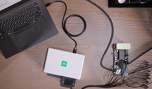
NI's new mioDAQ USB system has the performance and flexibility to accelerate time to market for a wide range of electronic and electromechanical systems. It starts with the use of USB type C connectivity. The mioDAQ USB quickly connects to a laptop or desktop computer with a single cable for data collection, analysis, and powering.

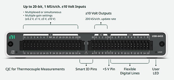
It offers up to 16 channels of 20-bit resolution, ±10 V measurements, and can support 1 million simultaneous samples per second. Plus, it has a variety of digital I/O and counter/timer channels for high performance, flexible test and product development systems (Figure 1).

Image of NI mioDAQ USB includes various I/Os (click to enlarge)Figure 1: This side of the mioDAQ USB includes various I/Os. The USB connector is on the opposite side. (Image source: NI)

The smart ID pins communicate with a user-supplied EEPROM so intelligence can be built into a test bench. An EEPROM can be connected directly to the spring terminal plug, or designed into prototype boards. The EEPROM can be queried to:

  • Confirm that the cables are plugged into the correct port
  • Capture device under test (DUT) information for use in channel and constant mapping
  • Automate metadata logging

Cold Junction Compensation (CJC) is used with thermocouples. It corrects for the temperature difference between the thermocouple's hot junction (where the temperature is being measured) and its cold junction (where the thermocouple wires are connected to the measurement system). CJC significantly improves the accuracy of thermocouple measurements, especially when the cold junction temperature fluctuates.

Robust performance

Designed to sit on a desktop, the mioDAQ is robust enough for use in fully automated test fixtures. It’s designed to maintain accuracy for up to 10 years without recalibration, making it suitable for use in manufacturing tests or field applications where frequent recalibration can hinder productivity. Models are also available with two-year recalibration cycles, which is ideal for lab bench testing and validation applications.

Self-calibration can adjust for differences in the operating environment and any manufacturing component variances. It’s initiated by simply clicking a button in the hardware configuration utility. The mioDAQ driver stores the self-calibration adjustments in an onboard EEPROM as a multivariable polynomial implemented without significantly impacting processing speed while providing superior performance compared to a simpler linear calibration equation.

Examples of measurements supported by the mioDAQ include:

  • Sensors and other ±10 V signals at up to 1 MS/s/ch
  • Voltage drops across shunt resistors
  • Battery voltages (±10 V peak measurement)
  • Power rails on USB or battery-powered designs
  • Pulse and event counting
  • Quadrature encoders
  • Resolvers
  • String potentiometers for measuring linear displacement
  • Low-voltage current sensors and transformers

Some mioDAQ devices support multiplexing to achieve higher channel counts. Multiplex mode uses a single analog-to-digital converter for multiple analog input channels. While that effectively increases the number of channels, it requires that the overall sample rate is shared by the multiplexed channels, reducing the sample rate for individual channels.

Also, control signals can be automated for a variety of functions like:

  • ±10 V output signals
  • Digital output signals
  • External relay (control with digital lines)
  • Generate pulse-width modulated signals
  • Simulating sensors
  • Connect to LEDs
  • Clocks and triggers

Four mioDAQ models, including part numbers 789887-01, 789882-01, 789888-01, and 789884-01, enable the user to purchase the exact performance needed to quickly design better products and pursue research activities (Table 1).

mioDAQ model USB-6421 USB-6423 USB-6451 USB-6453
Part number 789887-01 789882-01 789888-01 789884-01
Analog input channels (single-ended/differential) 16/8 32/16 16/8 32/16
Maximum sampling rate 250 kS/s (1 channel) 250 kS/s (1 channel) 1 MS/s/ch (8 channels) 1 MS/s/ch (16 channels)
Number of ADCs 1 1 8 16
Simultaneous* No No Yes Yes
Resolution 16-bit 16-bit 20-bit 20-bit
Analog output channels 2 4 2 4
Digital I/O channels 16 16 16 16
Counters 4 4 4 4
*USB-6451/53 have a multiplexed mode to achieve higher channel counts. See manual for details.

Table 1: mioDAQ USB is available in four models, enabling users to match performance to application requirements. (Table source: NI)

Under the hood

A solid understanding of device specifications and capabilities is needed to realize the maximum benefit. For example, mioDAQ supports three analog input terminal configurations.

Differential mode measures the voltage difference between two input terminals and can be used to minimize the effect of common mode noise. The referenced single-ended (RSE) mode measures the voltage of a signal for a specific reference point isolated from earth ground. When it is needed to measure the voltage of a signal for a floating or isolated ground with no external ground reference, the non-referenced single-ended (NRSE) mode can be used.

Separate timing engines allow for setting different rates for analog input (AI) channels, analog outputs (AO), and digital I/O (DIO) lines. For example, the user can choose to:

  • Synchronize systems to the same clock and use AI, AO, and DIO, all at the same rate and time
  • Trigger on an analog input voltage value
  • Trigger multiple subsystems starting at the same time with different run rates
  • Re-trigger data acquisition, acquiring a fixed number of samples based on a trigger, then reset and wait for the next trigger event

The NI mioDAQ USB Programmable Function Interface (PFI) is a series of digital I/O lines that can be configured as static digital I/O or used with counter/timer, triggering, and timing functions. They enable greater flexibility of control and monitoring.

For example, the PFI lines can be used for functions like analog acquisition, generating waveforms, or counter events. Software support, including the NI-DAQmx driver and configuration utilities, simplifies the process of using the PFI lines.

Quick start for a project

Inside the NI mioDAQ box, the user will find the hardware needed for a quick start including an NI mioDAQ, a 2-meter USB-C to USB-C cable with a locking screw (part number 789956-02), spring terminals (part number 785502-01), a backshell for the terminals to provide strain relief (part number 785080-01), and an NI screwdriver for tightening the locking screw on the USB connector. The cable, spring terminals, and backshell can also be purchased separately (Figure 2).

Image of NI mioDAQ comes with the connectorsFigure 2: The NI mioDAQ comes with the connectors and cables needed to start using and speed up development efforts immediately. (Image source: NI)

Software speeds setup and supports flexibility

The user begins mioDAQ setup by scanning the QR code on the device. That takes the user to the NI website page, where the necessary software and documentation can be downloaded. Available resources include the user manual, setup videos, pinout map, and software, including links to download FlexLogger Lite and drivers for LabVIEW, Python, and C/C# to ensure a smooth setup process and minimal setup time.

NI Measurement & Automation Explorer (MAX) free software provides access to NI hardware and acts as a central hub for interacting with NI hardware and software. It's automatically installed with all NI drivers and system configurations. MAX allows configuration of devices, troubleshooting of issues, and even creation of simulated devices for testing purposes without physical hardware.

NI FlexLogger Lite is a free software application for simple projects or new users who want to acquire and log data. Without programming, it lets the user quickly configure, visualize, and log data from sensors and other measurement devices.

FlexLogger Lite automatically detects NI DAQ hardware and provides sensor-specific configuration options. It enables real-time visualization of acquired data, allowing users to monitor measurements as they are being taken. It also supports logging data into common formats like Excel or binary .tdms files.

FlexLogger Lite is a companion to the full-featured FlexLogger software, and the user can choose to upgrade to the full version for more advanced features like automated testing, custom measurements, and scaling to multiple chassis.

For more complex needs, the user can turn to LabVIEW. It runs in Windows and Linux and provides a graphical programming language and development environment for automation, testing, and measurement applications. Its graphical interface makes it easier to visualize and understand complex processes than traditional text-based programming.

It's widely used in industries like aerospace, automotive, and process industries for automating measurements, testing, and data acquisition. It supports data visualization and analysis and real-time control with deterministic behavior.

For an even more powerful and comprehensive software environment, mioDAQ is compatible with the NI LabVIEW+ Suite, a bundled collection of NI test software designed to streamline the testing and validation processes. It’s a comprehensive suite of tools for automation, data acquisition, analysis, and reporting. Built on LabVIEW, key components of the LabVIEW+ Suite include:

  • NI TestStand test framework for designing, managing, and executing test sequences
  • InstrumentStudio for interactive instrument configuration and control
  • FlexLogger for quick and scalable data logging
  • DIAdem provides data analysis and reporting capabilities

Mounting options

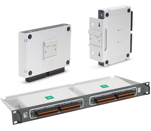
mioDAQ USB is more than a desktop device. The user has a selection of vertical or horizontal DIN rail, flat panel, and 19-inch rack mounting for building test stands and automation systems. The mounting kits are supplied with USB-C cables with right-angle connectors to complete the installation. Replacement USB-C connectors are also available, part number 789957-02. The mounting specifics include (Figure 3):

  • Horizontal DIN clip-only kit (part number 789986-01) is available for horizontal mounting on a standard 35 mm DIN rail. Includes a USB-C cable with right-angle connectors.
  • Vertical DIN rail and flat panel mounting using keyholes can be implemented using part number 789955-01. Includes a USB-C cable with right-angle connectors.
  • 19-inch rack mounting using part number 789953-01 that can mount up to two mioDAQ devices and includes two USB-C cables with right-angle connectors.

Image of NI mioDAQ mounting assembliesFigure 3: In addition to sitting on a desktop, mioDAQ mounting assemblies are available for horizontal DIN rail (top left), vertical DIN rail, flat panel mounting (top right), and in a 1U high 19-inch rack configuration (bottom). (Images source: NI)

Conclusion

NI’s mioDAQ USB gives the user the depth of hardware performance and the breadth of software tools needed to speed development of advanced electronic and electromechanical products and win the race to market. It starts with a simplified setup and configuration and continues with measurement calibrations guaranteed for up to 10 years. Models are available with various channel counts to optimize the configuration to the needs of the project. In every case, they provide the accuracy and precision the user demands.

Recommended reading:

  1. How to Build a Compact Data Acquisition System
  2. Test Software Bundle Simplifies the Creation of Test Programs
  3. How to Speed System Design, Validation, and Production Test Using Modular Instruments and Software
  4. Implementing a Compact and Flexible Automated Test System Using Multifunction PXI I/O Bundles
DigiKey logo

免责声明:各个作者和/或论坛参与者在本网站发表的观点、看法和意见不代表 DigiKey 的观点、看法和意见,也不代表 DigiKey 官方政策。

关于此作者

Image of Jeff Shepard

Jeff Shepard

Jeff 从事电力电子、电子元件和其它技术主题写作 30 余载。在其于 EETimes 任职高级编辑期间,他开始了电力电子写作。后来,他创立了一份叫《Powertechniques》的电力电子杂志,再后来又创立了一家全球性的研究和出版公司 Darnell Group。在开展各项业务的同时,Darnell Group 还发布了 PowerPulse.net,专门针对全球电力电子工程社区提供每日新闻。他是一本名为《Power Supplies》的开关模式电源教课书的作者,该书由 Prentice Hall 旗下 Reston 分部出版。

Jeff 还是 Jeta Power Systems 共同创始人,这是一家高功率开关电源制造商,后来被 Computer Products 收购。Jeff 也是一个发明家,其名下拥有 17 项热能收集和光学超材料美国专利,同时他也是掌握电力电子行业全球趋势的专家和网红发言人。他拥有加利福尼亚大学定量方法和数学硕士学位。

关于此出版商

DigiKey 北美编辑