Hardware Considerations when Running an RTOS on your MCU
投稿人:电子产品
2015-09-02
MCUs are called upon to control more and more functions within an embedded system. Often these functions are real-time in nature and require servicing at periodic intervals to meet system requirements for responsiveness, performance, or reliability. Often a Real-Time Operating system, or RTOS, is used to manage several real-time events to ensure responsiveness is sufficient to meet system requirements. Not all MCUs are appropriate for hosting an RTOS, however, so a review of some of the key capabilities that allow or facilitate hosting an RTOS on a specific MCU is useful to designers of real-time embedded systems.
This article will quickly review some of the key features available on modern MCUs that help when running an embedded system that requires an RTOS. This will help a designer to more efficiently select an MCU as an RTOS host, and to design the embedded system using that MCU.
Managing real-time response
As control systems become more complicated, it is increasingly difficult to manage the various MCU functions with a simple control routine. With multiple events with different priorities, a single control loop that is constantly checking to see what event needs service becomes unwieldy. The control loop just cannot get to every function quickly enough. What is needed is a real-time approach to control, where all events can be serviced within their required response time.
Often an MCU can achieve better control over complex systems by responding to an event, either an internal MCU request triggered by a timer or an external event triggered by an I/O signal, using an interrupt. Interrupts can be prioritized so that the most important requests are processed first, and with modern MCU interrupt systems, response times can be very fast. Unfortunately, proving that all events will be handled with the required periodicity can be difficult. For example, if we need to make a series of analog-to-digital conversions, while receiving data over a USB port and computing a low-pass filter on the acquired analog data, figuring out the maximum sample rate for the conversion may be very difficult.
Another option for improving real-time response is to use a real-time operating system or RTOS. In this approach every task in the control system can be assigned a time slice or portion of the MCU processing cycle. If the function doesn’t need the time allocated currently, it can “turn over” the time to another function so that precious processing cycles are not lost. If no functions require servicing an idle process, often in a low-power mode, can be initiated to save power. The allocated time slice can be adjusted to make sure a minimum amount of time is available to satisfy the required response time. With the right allocation to the analog-to-digital converter, the USB port, and the filter-processing functions the system will operate in a predictable and efficient manner.
Modern MCUs have been optimized to make it easy to implement RTOS implementations. Perhaps the most obvious is the inclusion of a dedicated timer, often the “timer tick” associated with determining processing allocation, which makes it easy to allocate time slices to functions. Intelligent peripherals that can execute tasks in parallel with other MCU activities are helpful as well since the associated process need only “fire off” the event and then can return control to another process. For example, a USB transfer could be started by simply programming the DMA controller to move SRAM data to the USB port. The task need not take any other activity until the buffer has been emptied or an error has occurred.
Let’s take a closer look at some of the most important RTOS-supporting hardware elements to better understand how we can optimize MCU-based RTOS implementations.
Using advanced interrupt controllers
Because RTOS-based systems need to respond to real-time events quickly and efficiently, an advanced interrupt system is perhaps the most important hardware element in an MCU-based design. For example, if the interrupt takes too many cycles to respond, perhaps because several CPU registers need to be saved prior to calling the interrupt routine, real-time response can suffer. Additionally, if the interrupt controller has only a small number of possible vector locations, the software may need several cycles to figure out the source of the interrupt. For example, an interrupt signaling transfer complete should be easily distinguished from a transmission error.
The Microchip PIC24F MCU has an advanced interrupt controller with several of the features desired when implementing an MCU-based RTOS. The block diagram of the PIC24F and dsPIC MCU family is shown in Figure 1. The interrupt controller, shown in gray in the middle of the diagram, connects all the peripherals, timers, and several input signals to provide comprehensive interrupt support. Up to 118 different interrupt sources are available with up to five from external sources. With five-cycle fixed-interrupt latency interrupt response times are fast enough for just about any application.

Figure 1: Microchip PIC24 and dsPIC DSC family block diagram. (Courtesy of Microchip)
The PIC24 and dsPIC DSC MCU interrupt controller also supports seven levels of priority, making it easy to distinguish between the most important events and the least important. This can be particularly useful when it is critical to respond to some events immediately and when some events can wait to be serviced. For example, acquiring data is typically much more important than processing it, so acquisition events are typically prioritized much higher than processing events.
Memory footprint and low power
Two of the most common concerns engineers have when switching to an RTOS-based implementation from a purely interrupt or control-loop design are memory footprint and low power. Since each RTOS process needs a special control block in SRAM to store various stated information for the process, engineers are often concerned that they will run out of SRAM and be “starved” of memory for their application. Luckily, RTOS memory footprints have been constantly improving as context switching times and control-block sizes have been optimized. Additionally, MCUs are including more and more SRAM on the device as this resource becomes less and less expensive to include while becoming more and more valuable.
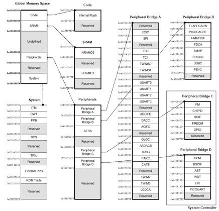
As an example, the Atmel SAM4L MCU offers either 32 Kbytes or 64 Kbytes of SRAM in two blocks—HRAMC0 and HRAMC1—as shown in the illustration of system-memory allocation in Figure 2. These SRAM blocks are accessed in a single cycle, a deterministic process that simplifies latency and performance calculations critical in RTOS-based systems. Having SRAM organized as two separate banks also improves performance for DMA-based functions since memory blocks can be allocated to each bank to optimize overall access bandwidth.

Figure 2: Atmel SAM4L MCU global memory allocation. (Courtesy of Atmel)
With each RTOS process only requiring a few hundred bytes, the full context for even a complex RTOS requires just a few percent of the MCU’s SRAM. A consideration often missed by some designers is that with an RTOS communication, buffers can usually be significantly reduced since the response time is smaller and more predictable. For some functions, the savings in SRAM will more than make up for the size of the context switching storage requirement.
Low-power modes are also fully supported in most RTOS implementations. This means that modes that reduce the internal regulation voltage, reduce clock speeds, or disable clocking to specific peripherals can all be utilized. The Atmel SAM4L MCU has some specialized controls that make it easy to adjust voltage levels and clock speeds for the requirements of each processing thread, if desired. Multiple “idle modes” can also be used to select between a few standard low-power settings, shared by multiple threads.
Simplifying Ethernet connectivity
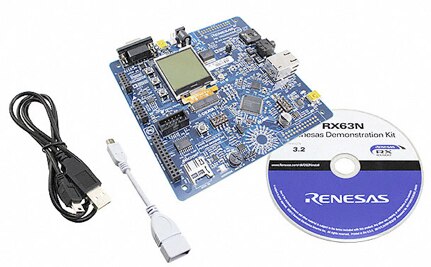
In real-time systems with high-speed connectivity requirements, such as Ethernet, the hardware on which Ethernet is important, but the supporting “hooks” that make it easy to implement should not be overlooked. For example, the Renesas RX63N has an advanced Ethernet controller with a dedicated Ethernet DMA controller that can directly manage the descriptors that control Ethernet transmission. This dramatically simplifies the control of Ethernet traffic since many of the low-level details can be controlled within the Ethernet subsystem. Additionally, the implementation of Ethernet connectivity in an RTOS environment can be simplified by the use of a connectivity development kit, illustrated in Figure 3, which can be bundled with the Micrium RTOS. This combination of the MCU, the development board, and the Micrium uC/OS-II or uC/OS-II RTOS provides a proven platform on which existing example code can be used as a first step in implementing a custom design.

Figure 3: Renesas RX63N ethernet kit with Micrium RTOS support. (Courtesy of Renesas)
The Micrium RTOS also provides a variety of middleware modules that further simplify connectivity applications. For example, IPv6 support makes it easy to implement even the most complex Ethernet subsystems. The availability of example designs means that getting a demonstration system working can be done in record time.
Efficient processing for DSP applications
In some applications an RTOS can be used to make sure processing is done as efficiently as possible. DSP applications, for example, can be processing hungry and if multiple communications channels compete for CPU cycles, efficiency can be significantly impacted. For example, the Texas Instruments TMS320C66xx DSP has significant processing capability. Just one of the processing cores shown in Figure 4 has eight separate processors (L/S/M/D 1 and 2) that can work in parallel. When using an RTOS, like the TI-RTOS, communications functions can be more easily managed to limit the number of CPU cycles required. This frees up processing time for the “heavy lifting” the DSP does to crunch the large amounts of data needed in most DSP-centric designs.

Figure 4: Texas Instruments TMS320C66xx DSP provides significant processing performance. (Courtesy of Texas Instruments)
Conclusion
Often, an embedded system needs to respond to events within a specified time and in these system an RTOS, hosted on an MCU, is a possible solution. Make sure you know the requirements for hosting an RTOS on an MCU so you can make the best MCU selection and ease the development of the resulting RTOS-based design.
For more information about the parts discussed in this article, use the links provided to access product pages on the DigiKey website.
免责声明:各个作者和/或论坛参与者在本网站发表的观点、看法和意见不代表 DigiKey 的观点、看法和意见,也不代表 DigiKey 官方政策。


