Generating Multiple Outputs from a Single Synchronous Buck Converter is Simple
投稿人:电子产品
2014-11-04
Many system boards require multiple voltage rails to drive a variety of semiconductor ICs spread across the board. For example, consider a modern set-top box (STB). It includes devices ranging from a system-on-a-chip (SoC) to chips like logic, Wi-Fi, HDMI, Ethernet PHY, and interfaces such as USB and SDIF. In addition, it also incorporates RF/IF functions and clocks and because all of these devices consume a lot of power, a fan is required for cooling. To minimize noise, a good design also separates analog and digital power rails. As a result, an SoC requires a core voltage of 1.8 V or lower while its I/Os need a 3.3 V supply. Likewise, a USB port uses 5 V supply and so does the fan. In short, a single-system board requires multiple power rails to operate.
Traditionally, to generate these multiple voltages, designers have been using multiple switching converters or low-dropout regulators (LDOs) to step-down voltages from the closest voltage bus. Besides adding to the cost and space of the system board, using multiple switching regulators or LDOs also means more power consumption and lower overall efficiency. An alternative, simpler approach would be to generate multiple voltages from a single synchronous step-down regulator.¹
Multi-output synchronous converters
Although, single-synchronous step-down regulators generating multiple-output voltages are available, such as Linear Technology’s LM5006, they use coupled inductors and associated multiple external MOSFETs, as well as diode rectification to generate two or more voltage outputs. A typical LM5006-based step-down converter using coupled inductors is shown in Figure 1. Additional components required generating two or more outputs use more space and add cost while compromising efficiency, and thereby defeating its use. Hence, to minimize external components while overcoming the cumbersome of designing transformers or coupled inductors, suppliers like Texas Instruments and Linear Technology have introduced next-generation integrated multi-output synchronous step-down switching regulators that simplify such tasks from a smaller footprint without compromising efficiency.

Figure 1: A dual-output synchronous buck converter using coupled inductors.
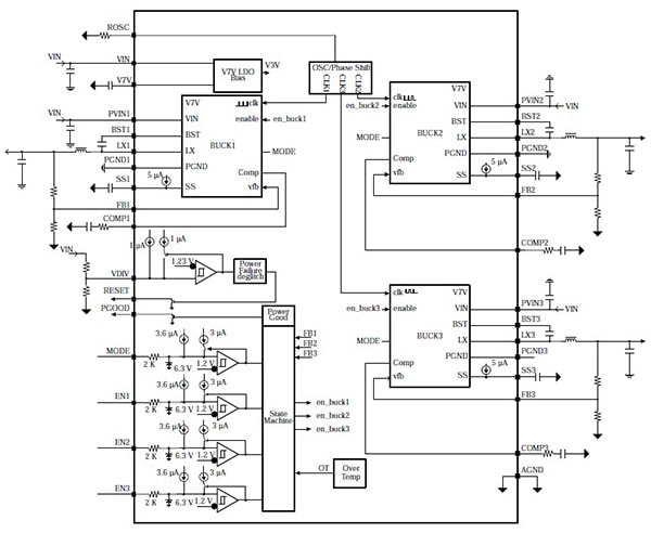
Take TI’s new family of multi-channel synchronous buck converters, such as TPS65261 (Figure 2). This monolithic, multi-channel synchronous step-down converter integrates three buck converters on-chip to enable three different voltage outputs from a single input supply with output currents rated at 3 A/2 A/2 A. As TI describes the part in its product datasheet, each buck converter is independent with dedicated enabled, soft-start and loop compensation pins. The feedback voltage reference for each buck on-chip is 0.6 V. Its wide input supply voltage range of 4.5 VDC to 18 VDC encompasses most intermediate bus voltages operating off a 5 V, 9 V, 12 V or 15 VDC power bus. The switching frequency of the converter can be adjusted from 250 kHz to 2 MHz with an external resistor. A similar part with slightly higher current rating is TPS65250. Buck 1 is rated for a maximum current of 3.5 A while buck 2 and 3 are each rated for a maximum current of 2.5 A. Unlike TPS65261, which comes in a 32-pin VQFN package, the TPS65250 is housed in a 40-pin QFN.

Figure 2: Functional block diagram of TI’s triple synchronous step-down converter TPS65261.
To minimize input filter requirements, the switching clock of an on-chip buck 1 is 180 degrees out-of-phase with respect to the clocks of buck 2 and buck 3, while the clocks of buck 2 and buck 3 run in-phase. Furthermore, to enable proper sequencing of the output voltages, the multi-output synchronous converter incorporates dedicated enabled and soft-start pins for each buck. What’s more, it features a power-good (PGOOD) pin to supervise each output voltage of the buck converters. In fact, the power-good pin asserts when any output voltages are out of operation. As a result, the converter is protected from overload and over-temperature fault conditions. In fact, according to TI, the internal thermal shutdown circuitry forces the device to stop switching if the junction temperature exceeds 160°C. The device reinitiates the power-up sequence when the junction temperature drops below the 140°C mark. Additionally, for higher efficiency at light load, the TPS65261 enters high-efficiency pulse-skipping mode (PSM) operation at light-load current.
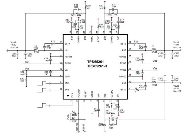
A triple-output synchronous step-down converter using TPS65261 is shown in Figure 3. Per the TPS65261 datasheet, the design parameters used for this triple-output converter are depicted in Table 1. Selecting the value of the output inductor, as well as the input and output capacitors is described in the datasheet of the product. Based on the converter’s current-mode-control scheme, the datasheet shows you how to select frequency and components for the loop-compensation circuit.

Figure 3: A triple-output synchronous step-down converter based on TPS65261.
| Design Parameter | Example Value |
| VOUT1 | 1.2 V |
| IOUT1 | 3 A |
| VOUT2 | 3.3 V |
| IOUT2 | 2 A |
| VOUT3 | 1.8 V |
| IOUT3 | 2 A |
| Transient Response 1 A Load Step | ±5% |
| Input Voltage | 12 V normal, 4.5 V to 18 V |
| Output Voltage Ripple | ±1% |
| Switching Frequency | 600 kHz |
Table 1: Design parameters for a triple-output synchronous step-down converter based on TPS65261.
Multi-output μModule regulators
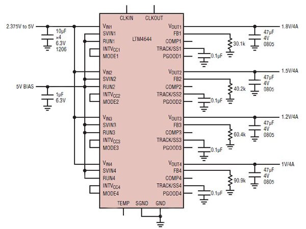
Similarly, Linear Technology has introduced a quad-output step-down μModule regulator designated LTM4644 and configurable as a single-, dual-, triple-, or quad-output solution. This flexibility enables system designers to rely on one simple and compact μModule regulator, says Linear Technology. According to the company, there are four independent regulators with associated DC/DC controllers, power switches, inductors, and compensation components in a 9.0 x 15.0 x 5.01 mm BGA package. Each regulator is capable of delivering up to 4 A continuous output current. Only eight external ceramic capacitors and four feedback resistors are required to regulate the four independently adjustable outputs between 0.6 V to 5.5 VDC, as shown in Figure 4. Separate input pins enable the four channels to be powered from different or a common supply rail(s) from 4 VDC to 14 VDC. The LTM4644 is ideal for applications in communications.

Figure 4: Linear Technology’s quad DC/DC μModule regulator requires only a handful of external ceramic capacitors and feedback resistors to regulate four independently adjustable outputs between 0.6 V to 5.5 VDC.
For lower-output currents, Linear offers the LTC3544, which is a quad-synchronous step-down regulator with four independent outputs that provide up to 300 mA, 2000 mA, 200 mA and 100 mA output current, respectively. However, the input voltage range is limited to 2.25 V to 5.5 V. It is recommended for Li-ion/polymer battery-powered applications and comes in a low-profile 16-lead QFN package. Similarly, for automotive application, Linear offers its LT3504 regulator.
For applications that require triple outputs, Linear has introduced the LT3514 comprising three buck regulators offering 2 A, 1 A and 1 A output currents, respectively. The device has a wide operating input range of 3.2 V to 36 V. An on-chip boost regulator allows each channel to operate up to 100 percent duty cycle.
In summary, there are a number of sources available today that offer integrated multi-output synchronous step-down DC/DC converters and regulators that simplify the task of designing buck converters with multiple output voltages using a single-input voltage range. Due to high integration on-chip and inside the package, only a handful of external components are needed to complete such a multi-output solution.
For more information on the parts discussed in this article, use the links provided to access product pages on the DigiKey website.
Reference
- “Simple Step-down Regulator Generates Multiple Voltage Rails with Good Efficiency and Regulation” by Vijay Choudhary, Texas Instruments, May 2011.
免责声明:各个作者和/或论坛参与者在本网站发表的观点、看法和意见不代表 DigiKey 的观点、看法和意见,也不代表 DigiKey 官方政策。


