Digital Voltage Regulator Control Using PMBus
投稿人:电子产品
2013-06-04
Digital control optimizes the efficiency, line, and load regulation of a DC-to-DC switching voltage regulator. Engineers are able to adapt the regulator’s closed-loop response, for example, to perfectly match the demands of their product.
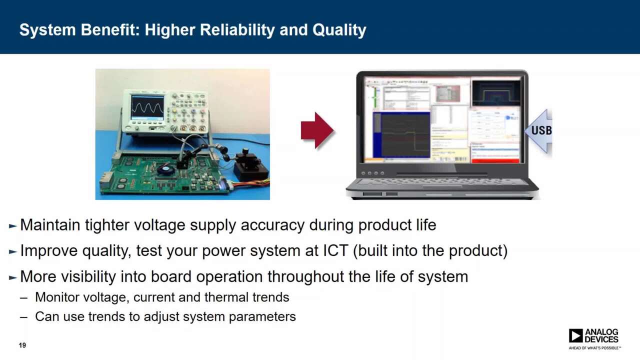
However, digital control really comes into its own in a more complex system that comprises several regulators. The individual devices can be supervised by a centralized power system host control via a digital communications bus such as the standardized Power Management Bus (PMBus). The host could be an IC dedicated to power system control, a general-purpose microcontroller, laptop computer with graphical user interface (GUI), or an ATE (used during the power supply or system testing process).
This article examines PMBus, describes how it works, and identifies some of the digital power chips that have embraced the technology.
The basics
PMBus is based on the System Management Bus (SMBus) typically found in computer motherboards for communication with the power source. However, while SMBus is designed for communication with low-bandwidth devices, PMBus is targeted at digital management of power supplies, components, and power-related chips such as a rechargeable battery subsystem or temperature-, fan- and voltage-sensors and clock chips.
SMBus itself was based on Inter-Integrated Circuit (I²C), the serial single-ended computer bus originally designed by Philips and used for attaching low-speed peripherals to a motherboard or other embedded system. As a result of this foundation, PMBus is a relatively low speed, two-wire communications protocol. However, unlike SMBus and I²C, PMBus defines a substantial number of domain-specific commands rather than just detailing how to communicate using commands defined by the reader.
In March 2005, version 1.0 of the PMBus specification was published. More recently a revised specification, version 1.2, was released. The standard is owned by the System Management Interface Forum (SM-IF) and is royalty-free. The PMBus sub-section of the forum comprises more than 30 adopter companies including major power chip silicon vendors such as Analog Devices, CUI, Emerson Network Power, Intersil, Linear Technology, Maxim, and Texas Instruments (TI). The organization claims adoption of an interoperable standard enables digital power control to be adopted without the need to unduly burden the host system with multiple protocols.
Digital power control
Analog DC-to-DC voltage regulators offer stable output voltages and high efficiency performance. However, in the case of the integrated modules typically used for point-of-load (PoL) applications, the engineer is restricted – with the exception of some minor changes to loop response by changing input and output filter components – to the operating parameters selected by the supplier. While those parameters work well for most anticipated operating conditions, there are inevitably some trade-offs.
In contrast, with digital power devices, designers can take advantage of features such as the ease with which the technology enables optimization of the power supply by adaptation of its closed-loop response – even allowing adjustment “on-the-fly” to suit changes in the operating environment or to compensate for factors such as capacitive loading and component aging.
This flexibility is a benefit in many designs, for example, in a portable product where the engineer is tasked with maximizing battery life, or where precision control over output voltage is critical such as when powering DSPs or ASICs. As an example, Figure 1 shows the circuit of a digital step-down (“buck”) voltage regulator.

Figure 1: Schematic of digital buck voltage regulator. (Courtesy of Emerson Network Power.)
Four main signal lines
SM-IF describes PMBus as “a standard way to communicate with power converters over a digital communications bus.” The forum says that the standard will work with all types of power converter including AC-to-DC power supplies, isolated DC-to-DC voltage regulators, and non-isolated PoL voltage regulators.
The standard does not define power supply characteristics such as form factor, pin out, and efficiency (this is left to organizations such as Point-of-Load Alliance (POLA) and Distributed-power Open Standards Alliance (DOSA). For more information, see the TechZone article “An Introduction to Board-Mounted DC/DC Converter Bricks.” There is also no provision for communication directly between converters to facilitate information exchange such as current sharing and analog voltage tracking.
There are some basic requirements for devices adopting PMBus, including safe start up without any bus communication; operation with or without a power-system manager or controller; support for “set and forget” (that is, programmed once at time of manufacture and then able to operate forever without any bus communication), and capability to access default settings from non-volatile memory or pin programming.
The PMBus protocol is defined in a layered manner and defines the rules for sending blocks of data from node-to-node in the network. The protocol’s two-wire serial bus physical layer is enhanced compared with SMBus, providing greater functionality for power control applications. The command language layer defines the commands, data formats, and information handling.
The two main signals connecting the host with each controlled device are DATA and CLOCK. In addition to these two mandatory signals, there are optional extensions to PMBus. A line called CONTROL can extend from the host to one or more controlled devices. The CONTROL line is used to define on and off conditions for controlled devices in a manner similar to the “remote control” and “Inhibit” signals that are commonly used with conventional power converters. Another optional signal, called SMBALERT#, is an interrupt that goes from a controlled device to the host for notification of a problem or situation that needs the host’s attention.
Figure 2 illustrates these four main signal lines. Data flows in the direction indicated, configure and control commands flow from the host to the controlled devices, and monitoring information flows from the controlled devices to the host. Both of these information transfers occur by using the DATA and CLOCK lines under control of the host.

Figure 2: Typical PMBus connection schematic. (Courtesy of SM-IF.)
Each controlled device has a unique 7-bit physical address, although PMBus does not specify how these addresses are established. This is because there are several methods for accomplishing the addressing and flexibility is important, allowing different hardware suppliers to use different address assignment methods and yet still be compatible with the PMBus.¹
PMBus expands
Silicon vendors that are part of the forum have wasted no time in adding PMBus capability to their products.
Analog Devices, for example, features the ADM1075 48 V Hot Swap Controller and Digital Power Monitor with PMBus Interface among its digital power chip offerings. The device is a full feature, negative voltage, hot-swap controller with constant power foldback and high accuracy digital current and voltage measurement. The company says the chip can be safely inserted and removed from a live –48 V backplane. The chip provides precise and robust current limiting and protection against both transient and non-transient short circuits and overvoltage and undervoltage conditions. The ADM1075 operates from a negative voltage of –35 to –80 V and, due to shunt regulation, is said to have good voltage transient immunity.
Linear Technology offers a DC-to-DC buck switching regulator controller with a PMBus interface. The LTC3880’s digital interface allows operating parameters to be set via remote control, and voltage, current, internal/external temperature, and fault status can be read back through the bus.
The controller uses a constant frequency, current-mode architecture and incorporates a 5 V linear regulator. The regulator provides 0.5 to 5.5 V output from a 4.5 to 24 V input. Figure 3 shows an application schematic for the LTC3880.

Figure 3: Application schematic for Linear Technology’s LTC3880 voltage regulator controller.
Maxim also offers several digital parts with the PMBus interface, including the MAX8688. The chip is programmed using the PMBus protocol. Once the configuration is complete, results are saved into an EEPROM or loaded onto the part through the bus at power-up. The company notes that the PMBus capability allows remote configuration of any regulator using the MAX8688, replacing expensive recalls or field service.
The MAX8688 is a fully integrated, digital power-supply controller and monitor chip that the company says works with any existing PoL power supply to provide complete digital programmability. By interfacing to the reference input, feedback node, and output enable, the MAX8688 takes control of the POL to provide functions such as tracking, sequencing, margining, and dynamic adjustment of the output voltage.
PMBus offers manufacturers and design engineers alike a digital power control protocol – based on a simple, robust, and established bus – that can be used to maximize the potential of the latest generation of digital chips coming onto the market. Expect to see its inclusion become a standard part of more new chips in future. For further information on the parts mentioned in this article, use the links provided to access product pages on the DigiKey website.
References
- “Introduction To The PMBus™,” Robert V. White, Artesyn Technologies and Chair, PMBus Specification Working Group, May 2005.
免责声明:各个作者和/或论坛参与者在本网站发表的观点、看法和意见不代表 DigiKey 的观点、看法和意见,也不代表 DigiKey 官方政策。