Design and Shielding Techniques to Block EMR and EMI
投稿人:电子产品
2012-05-03
The ever-improving functionality of modern smartphones, pods, tablets, and PCs is a testament to the designer’s ability to do more in less space. However, as silicon geometries get smaller, sensitivity to noise can get higher. This is problematic, for example, when trying to recover very low level signals through an antenna. In addition to providing immunity from surrounding noise, the designer also faces a critical need to squelch emissions to meet strict electromagnetic radiation (EMR) and radio frequency interference (RFI) compliance regulations. In 1982, in addition to emissions standards, the FCC was given the authority to regulate the susceptibility of consumer electronic devices to EMR.
This article describes techniques and products that can shield sensitive areas from outside interference and help designers control emission levels. All devices, materials, components, data sheets, and training materials are available online on the DigiKey website.
The problem
Digital systems typically have many clocks running. Add in the fact that designers prefer sharp, clean edges on digital lines (fast rise and fall times), and that the sharper the edge, the more harmonics result. It is easy to see why, with so many frequencies in play, there is radiation all around. A signal path that is 1/4, 1/2, or the wavelength of the clock frequency becomes an antenna, and 90-degree direction changes (such as vias on a printed circuit board), can become radiation points as well.
Fortunately, while the clock frequencies in our designs have been increasing in number and frequency, the logic voltage levels have been decreasing. Since radiated power is proportional to the voltage swings, the transition from early low frequency 12 V CMOS logic levels to modern 3.3 to 1.8 V logic levels has made the engineer’s life a bit easier in the quest to control radiated power. On the other hand, this blessing can also prove to be a curse, as lower level signals are more susceptible to noise and interference from local sources. Let’s look at what can be done.
Shielding assemblies
Since electromagnetic energy can be reflected, directed, or absorbed, this is where good design techniques and shielding can help. The Faraday cage is the best technique to ensure solid shielding. However, very few designs are islands unto themselves. Instead, there are inputs, outputs, and user interfaces. As a result, solid cages are the toughest to implement.
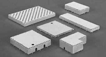
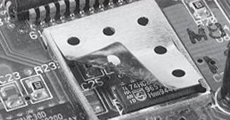
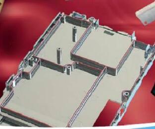
Thankfully, several well-engineered off-the-shelf shielding subassemblies are available (Figure 1). Board mounted shields such as the Laird BMI-S-105 come in a variety of sizes and shapes that can be accommodated on our printed-circuit boards. These solder to the boards and have vent holes to allow outgassing during the soldering process. Peel-away top coverings are available to gain access during development and to seal the tops electromagnetically if needed (Figure 2).
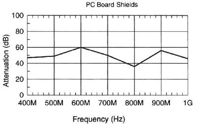
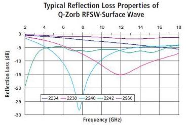
Unless a solid enclosure is used, some signals will be able to penetrate and/or radiate. Manufacturers such as Laird provide attenuation plots which indicate the frequencies and levels at which an enclosure attenuates (Figure 3). For more information, a training module on EMI shielding devices and techniques is available on the DigiKey website.
An example of a solid top cover comes from Würth with its 36003200 20 x 20 mm shielded top cover. Another interesting approach comes from Foto-Fab with its form-by-hand tin plate and brass standard RF shields such as the 2.0 X 3.0 X 0.50.
If you need to make your own shielded enclosures, there are RF accessories that make this an easier task, including PC board mounted fingers, tables, and clips. Springy clips such as the Harwin S1791-42R, for example, can provide retention force for a shielding assembly while providing a shield ground conductive feed. Similarly, standard contacts like the Laird BMI-C-001 provide spring-loaded axis profiled conduction points.
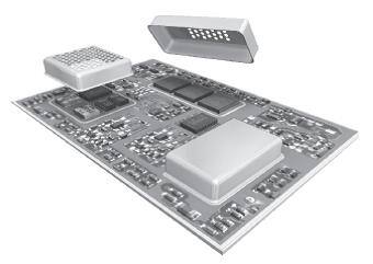
These types of metal-formed mini cages and associated connect techniques are typically used with demanding medical, telecommunications, CATV, telemetry, and radar applications. The aforementioned products also allow you to use standard printed-circuit board technology and achieve a (somewhat) compartmentalized partitioning (Figure 4).
The most solidly engineered Faraday-cage-types of enclosures are used in secure military designs, especially for communications and encryption. A very demanding classification known as Tempest uses compartmentalized metal enclosures and clever geometric placements to isolate functional stages and control signal flow (Figure 5). Each sensitive or potentially emitting stage is completely surrounded. Signals pass from one stage to another through the use of devices such as feed-through capacitors.
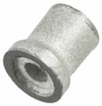
Feed-through capacitors such as the Tusconix 4400-680LF allow you to make high-pass, low-pass, band-pass, and notch types of filters through the interconnects from stage to stage. A press-fit leadless version like the 2463-001-X5S0-471MLF can be used in a more automated fabrication environment (Figure 6).
For chassis-partitioned, low-noise designs, these types of filter parts reduce emissions and susceptibility and come in leaded, leadless, turret, hook, soldertail, and press-fit configurations. A Tusonix training module on feed-through capacitors and filters is available on the DigiKey website.
Very few designs need this level of protection. For most applications simpler, lower-cost, and lower-weight shielding materials and meshes will suffice.
In some cases, a mesh is very effective at blocking EMI/EMR, as long as the mesh size is smaller than the wavelengths of concern. If the wavelength is smaller than the mesh opening size, it will penetrate, albeit at an attenuated and somewhat scattered level.
Not every mesh, however, is the same. The hardware-store-variety, metal-screen-door-type mesh material may be readily available and low cost, but it may not have the characteristics of a material specifically made for shielding applications. What is more, this material fractures as it ages and weathers poorly.
Stick-ons
An effective technique for use with or without a shielded enclosure is an adhesive-based shielding material. A stick-on shield sheet such as the Laird 3536-S is composed of magnetic particles in a polymer binder that absorbs energy in the 50 MHz to 3 GHz range. High-temperature versions like the Laird 5206-S are rated for –85° to 250°F and are lightweight and flexible. Caulk-like adhesives and sealers can even provide conductivity for demanding, compartmentalized designs (Figure 7).

In addition to formed enclosures and sheets, gaskets, tapes, foils, and acrylics are at our disposal to quiet down a noise node or protect a low-level input signal from a harsh and noisy environment.
Electrically conductive elastomers and foams like the Laird 4245PA51H01800 can not only protect from an emissions/susceptibility point of view, but also help absorb shock and vibration.
Ferrite materials like the TDK IRL02A 200X200X1 also suppress shock as well as magnetic intrusion and, just as the Laird ferrite sheets, are designed specifically for applications such as RFID (Figure 8).
General-purpose foil tape types of products like the 3M 1181 X 1", for example, are also very useful as final fixes on the assembly line floor. They not only seal corners and apertures in formed shield cases, but also can conduct away heat from critical areas. Make sure to lay out your PCB so to be able to accept these fixes by leaving a little space without traces for the adhesive metal tape.
Summary
Board-level shielding has become an important component in wireless circuit designs. With the size of circuit boards shrinking and the number of electronic devices increasing, the need for cost/effective protection solutions is growing quickly. An example of this is in the automobile where radio, navigation, hands-free phone use, and even wireless Internet access are all placed in close proximity on the dashboard. It is critical that all of these circuits work correctly together in the presence of other circuits without interference.
This article has discussed products and techniques that enable engineers to limit the electromagnetic emissions of their designs and reduce the susceptibility of circuits to EMR and EMI so as to achieve regulatory designated levels. For more information on the products mentioned, use the links provided to access product pages on the DigiKey website.
免责声明:各个作者和/或论坛参与者在本网站发表的观点、看法和意见不代表 DigiKey 的观点、看法和意见,也不代表 DigiKey 官方政策。


