Data Communication Drives M2M Automation Processes
投稿人:Convergence Promotions LLC
2013-06-05
Network connectivity is becoming the default method for machine-to machine (M2M) connectivity for embedded systems and mobile/portable devices over point-to-point protocols. These systems utilize a number of data formats and networking methods ranging from wireless options to full high-speed LAN/WAN environments.
There are two main methods for achieving this connectivity: a supplementary network controller that is added to an existing connection of an existing design; and the incorporation of the networking protocol and interface through an embedded function in their microcontroller and sensor subsystem. One of the key features of these applications is the software and firmware control required to develop these interfaces and their associated development environments.
Legacy systems
Most embedded systems that have been deployed in the field now need to be connected to a network in order to provide automated monitoring of their progress and system health. The challenge is how to bring this new functionality without having to re-qualify the whole design or, worse, change the firmware for the system and have to re-verify correct operation. The two methods that are most convenient for these current designs involve adding networking functions to an existing port on the system or adding a network adapter chip to the PCB that interfaces directly with the microcontroller.
One of the common ports in these legacy designs is the serial ports. Typically used for data collection and data transfer, these ports have been shifting from the older RS-232 interface to USB. The USB protocol includes local configuration firmware that allows the system to auto-configure and self-adjust to the device that is connected to the port. In addition to being auto-configured, the USB port allows for self-powered devices. This setup works quite well with products like Digi International’s XStick® XU-A11 USB to XBee® transceiver.
Available in both XBee PRO and ZigBee® PRO protocols (see Figure 1), the self-contained wireless transceiver supports 802.15.4 devices in a USB-powered package with integrated wireless antenna and analog front-end. The USB to XBee wireless personal area network adapter (WPAN) provides local connectivity for access, configuration, and network commissioning and is available in self-healing, self-configuring ZigBee mesh or fast 802.15.4 multi-point versions.

For systems that can support a board modification or a plug-in card to add the connectivity, solutions such as Texas Instruments’ TLK1201IRCP Ethernet transceivers are available. This single-chip device operates at a low 2.5 volt and has a version that is hot swappable for high-availability applications.
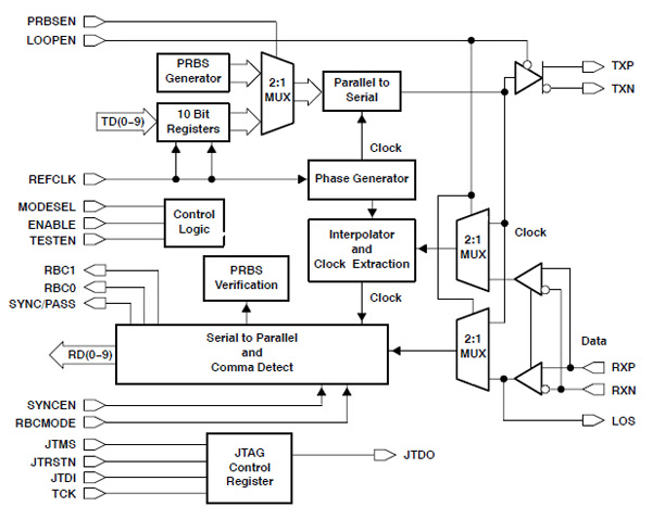
The TLK1201IRCP Ethernet transceiver is designed to add ultra-high-speed, full duplex, point-to-point data transmissions to a standard microcontroller-based system. This device supports the timing requirements for the 10-bit interface specification under the IEEE 802.3 Gigabit Ethernet specification, and is compliant with the ANSI X3.230-1994 (FC-PH) fiber channel standard. The device can support data rates from 0.6 Gbps to 1.3 Gbps. A block diagram for the TLK1201 Ethernet transceiver is shown in Figure 2.

For embedded applications, the chip is designed to send data over the various transmission media including printed circuit board traces, copper cables, and fiber-optic cables. The data rate and connection length for the data transfer depends on the signal attenuation characteristics of the media and the noise coupling in the signal environment.
The TLK1201 performs all the necessary data serialization, deserialization, and clock extraction functions for a PHY device. The transceiver operates at 1.25 Gbps (typical), which translates to a data bandwidth of up to 1 Gbps on copper or optical fiber media. For maximum compatibility with current and legacy systems, the TLK1201 supports both the specification’s 10-bit interface (TBI) and the reduced 5-bit interface utilizing double data rate (DDR) clocking. In the TBI mode, the serializer/deserializer (SERDES) accepts 10-bit wide either 8b or 10b parallel encoded data bytes.
Other connection options
For some applications, such as automotive networks, there is no main controller to handle the data management. As a result, communication methods such as CAN are used when there is no host controller. The CAN bus is a message-based protocol, designed specifically for automotive applications, but is now also being used in other areas such as industrial automation and medical equipment.
CAN is a multi-master broadcast serial bus standard for connecting electronic control units (ECUs). The protocol allows each node to be able to send and receive messages over the bus, but not simultaneously. Messages that are sent consist of an identifier, which acts as the definition of the priority of the message, along with up to eight data bytes. The data is transmitted serially onto the bus. The bus is managed with a signal pattern that is encoded in non-return-to-zero (NRZ) and is simultaneously sensed by all nodes.
The devices that are connected by a CAN network are typically sensors, actuators, and other control devices. These devices are not connected directly to the bus, but through a host processor and a CAN controller such as Texas Instruments’ SN65HVD1050DR RMC CAN transceiver.
If the CAN bus is free, any node may begin to send data. If two or more nodes begin sending messages at the same time, the message with the more dominant ID or priority (which has more dominant bits, i.e., zeros) will overwrite other nodes' less dominant IDs. Eventually (after this arbitration on the ID) only the dominant message remains and it is received by all nodes. This mechanism is referred to as priority-based bus arbitration. Messages with numerically smaller values of IDs have higher priority and are transmitted first.
As a CAN transceiver (see Figure 3), this Texas Instrument part provides a differential transmit capability to the bus and differential receive capability to a CAN controller at signaling rates up to one megabit per second. Designed for operation in especially harsh environments, the SNHVD1050DR features cross-wire, over-voltage, and loss of ground protection from -27 to 40 volts; over-temperature shut down; a -12 to 12 volt common-mode range; and the ability to withstand voltage transients from -200 to 200 volts in accordance with ISO 7637. The medical electronics community is starting to embrace this bus technology because of its high electromagnetic immunity (EMI) and very low electromagnetic emissions (EME).

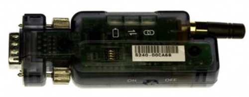
Another option for legacy systems that are dealing with small data-length transfers is to use a wireless Bluetooth® connection. This system is similar to Wi-Fi® and mesh networks in that they require a firmware set to handle all of the data interfaces, an analog front end, an antenna system, and a protocol for the data transfer. Complete solutions such as Microchip’s RN-220XP Bluetooth adapter can be used for standard 9-pin RS232 connections (see Figure 4). The self-contained unit can start sending data as soon as it is connected. It includes an integrated Li-poly rechargeable battery that operates up to 32 hours. This enables the unit be used for data monitoring and signal transfer during maintenance and on-site systems upgrades without having to manually configure the main equipment or provide external power. The connection supports baud rates from 1200 to 232.4 Kbps. The unit is remote configurable on the serial interface via the Bluetooth connection. The device also supports advanced triggering modes that sense incoming data and auto-connect and disconnect as needed to save power.

Integrated systems
For new systems that are microcontroller-based, the preferred method of communication is to use an MCU that has an integrated communication port and protocol handler. As the end applications are not known in advance of creating the MCUs, they tend to include multiple communication protocols and connection capabilities. The most common are USB 2.0, 10/100Mbps Ethernet, CAN, and JTAG. Examples include Microchip’s PIC32MX764F128H with embedded Flash and Renesas’ RX62N.
Microchip’s PIC32MX5/6/7XX microcontroller series use an MIPS32® M4K® processor at the core. The core features a simple dual-bus interface with independent 32-bit address and data busses. In this interface, the transactions can be aborted to improve interrupt latency. The core also has an EJTAG debug and instruction trace, which has support for single stepping, virtual instruction and data address/value, breakpoints, and PC tracing with trace compression.
The communication interfaces start with standard functions of six UART modules with RS-232, RS-485, and LIN support; an IrDA interface with on-chip hardware encoder and decoder; and up to four SPI modules and five I²C modules. USB, CAN, JTAG, and Ethernet supplement these standard MCU interface blocks.
PIC32® MCUs have a USB DMA controller that transfers data between the data buffers in RAM and the SIE. The register interface allows the CPU to configure and communicate with the module. The PIC32 USB module includes USB full-speed support for the host and the device, low-speed host support, USB OTG support, integrated signaling resistors, integrated analog comparators for VBUS monitoring, an integrated USB transceiver, hardware transaction handshaking, endpoint buffering anywhere in system RAM, and an integrated DMA to access system RAM and Flash. This USB interface allows the PIC32 CPU to address wireless data communication protocols that are not part of the core SoC.
The CAN interface for the PIC32 addresses all of the CAN 2.0B compliance specifications with data rated up to one megabit per second. The CAN message reception and transmission functions include thirty-two message FIFOs, where each FIFO can have up to thirty-two messages for a total of 1024 messages; each FIFO can be a transmit message FIFO or a receive message FIFO; user-defined priority levels for messages; thirty-two acceptance filters for message filtering; four acceptance filter mask registers for message filtering; an automatic response to remote transmit request; and low-power operating modes. The CAN module is a bus master on the PIC32 system bus.
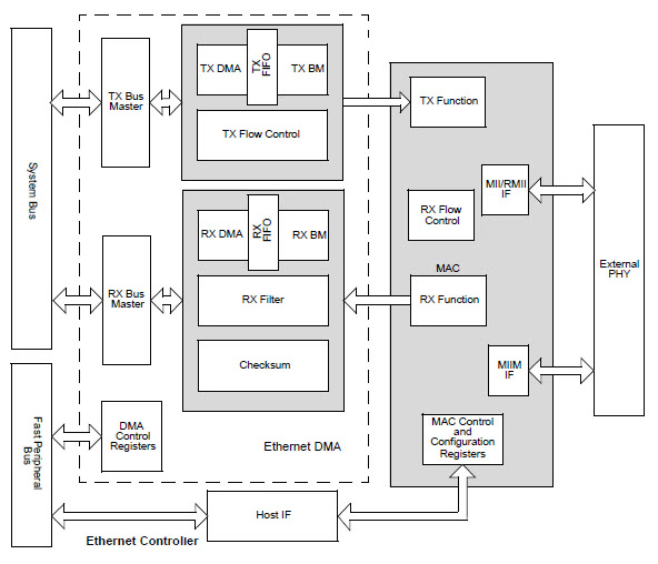
The PIC32 features an Ethernet controller that is a bus master module. It needs to interface with an off-chip physical layer (PHY) to implement a complete Ethernet node in a system as shown in Figure 5. The internal Ethernet controller supports the following functions that are drivers for the external PHY: 10/100 Mbps data transfer rates; full-duplex and half-duplex operation; RMII and MII PHY interface, MIIM PHY management interface; both manual and automatic flow control; RAM descriptor-based DMA operation for both receive and transmit path; and fully configurable interrupts.

The device also has configurable receive packet filtering. The configurable options include a CRC check; a 64-byte pattern match for broadcast, multicast and unicast packets; Magic Packet™; a 64-bit hash table; runt packet and packet payload checksum calculation.
Advanced microcontrollers
On the high end of embedded controllers is Renesas’ RX62N. This is a full 32-bit CPU with a single-precision 32-bit IEEE-754 floating point processor; an accumulator that is configured as a 32 × 32 to 64-bit result that runs in one instruction cycle; a Multiply/ Divide Unit with a 32 × 32 Multiply in one CPU clock for multiple instructions; and a CISC/Harvard Architecture with 5-stage pipeline. The SoC has built-in logic to support TFT-LCDs up to WQVGA resolution and up to twenty Extended Function Timers.
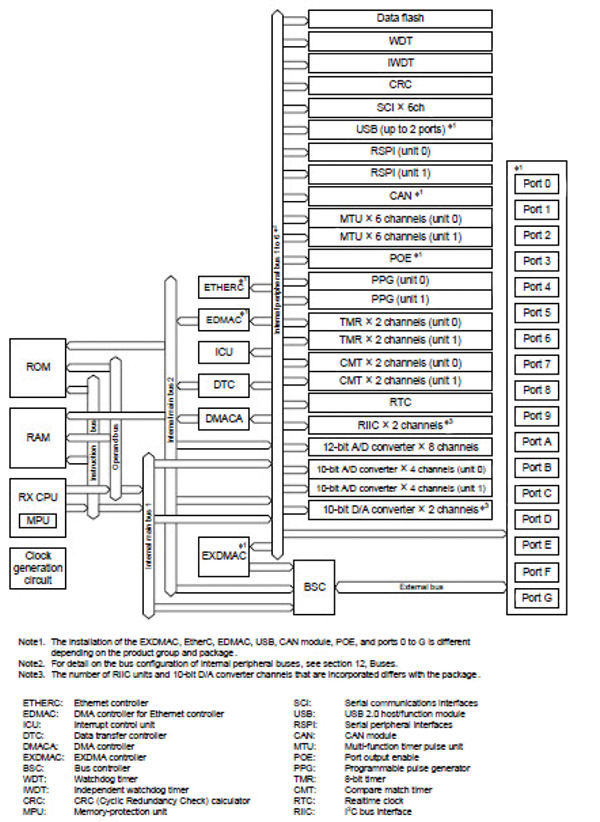
A key feature of this chip is the support for up to fourteen communication interfaces to external connections. They include USB 2.0 Full-Speed interfaces with PHY (2 channels) that supports Host/Function/OTG and ten endpoints (control, interrupt, bulk, and isochronous); an Ethernet MAC 10/100 Mbps with half- or full-duplex support for one channel; a dedicated DMA with two kilobyte transmit and receive FIFOs; an RMII or MII interface to the external 10/100 Mbps PHY; a CAN system that is ISO11898-1 compliant and supports one channel with thirty-two mailboxes; asynchronous, clock sync, smartcard, and 9-bit mode (six channels) SCI channels; I²C interfaces up to one megabit per second with SMBus support (two channels); and finally two channel RSPI.
The architecture of these SoCs is shown in Figure 6. These blocks includes 128 GPIO channels, two channels of 10-bit DACs, and an ADC that can be configured as one 12-bit x 8 channels with a single sample and hold or as two 10-bit x 4 channel ADCs, each with a sample and hold.

There are several Product Training modules on DigiKey’s site that explain how to set up and configure an Ethernet interface. Training solutions from Freescale Semiconductor’s MCF51CN, Microchip Embedded Ethernet, NXP Semiconductors LPC3250, and STMicroelectronics STM32 overview embedded and standard Ethernet connectivity. The training modules refer to SDKs that are available to help with the implementation by specific parts.
Summary
As machines become more autonomous in their activities, the need for connectivity to a network for procedure and data storage and processing is becoming a minimum requirement. This has resulted in the retrofit and supplemental design addition of the network component to the systems using both wired and wireless protocols. This trade-off is made based on location and quantity of data being communicated.
For new designs, the incorporation of the networking communication interface directly into the microcontroller and sensor subsystems is becoming the norm. The ubiquity of these connection methods is changing the scope and capabilities of real-time systems in applications from consumer through industrial.

免责声明:各个作者和/或论坛参与者在本网站发表的观点、看法和意见不代表 DigiKey 的观点、看法和意见,也不代表 DigiKey 官方政策。


