Control for Advanced Motion
投稿人:DigiKey 欧洲编辑
2013-06-12
This article will provide an overview of control strategies for AC motors that satisfies the demand for greater accuracy and energy efficiency. Products discussed will include DSPs and digital signal controllers made by Analog Devices (Blackfin), Freescale Semiconductor (56F800), Microchip Technology (DSPIC33FJ) and Texas Instruments (C28x).
Advanced motion control is a key element of automation processes, providing the ability to maneuver heavy loads into precise positions, but the energy efficiency of the motors is a key concern today. Flux-vector and matrix-based control techniques make it possible to use feedback from the motor windings themselves to determine the position of the target and provide maximum torque when it is needed.
Using algorithms such as Kalman filters can demand high performance signal processing, supported by architectures such as DSPs and DSCs as discussed in this article.
The largest single consumer of electricity worldwide is the motor, responsible for twice the consumption associated with lighting according to a report published in 2011 by the International Energy Agency (IEA). A very large proportion of them represented AC motors. Although they are relatively inexpensive, AC motors have the downside of being energy inefficient. By 2030, without comprehensive and effective energy‐efficiency policy measures, energy consumption from electric motors is expected to rise to 13,360 TWh per year and carbon dioxide emissions to 8,570 Mt per year. Advanced electronic control strategies are expected to slow down this increase.
Through electronic control, it is possible to improve the efficiency of AC motors to the degree that, with the right signal-processing algorithms, they become cheaper to run than more complex and expensive DC motors.
The IEA says that if all countries adopted best practice for industrial electric motors, by 2030 approximately 322 TWh of annual electricity demand would be saved, giving rise to corresponding savings of 206 Mt of carbon dioxide emissions.
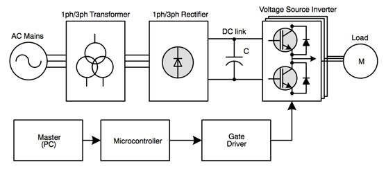
The key to better efficiency is to provide only the energy required by individual phases with the motor at any given time. This is in stark contrast to traditional control techniques that calculated the average power needed to drive the motor. In its most basic form, all that a motor controller has to do is supply current to coils within the stator in sequence to generate a magnetic field that causes the rotor to move.

Figure 1: The architecture of a typical motor-control system.
The simplest control technique is volts-per-hertz. It can be readily implemented on a basic 8-bit microcontroller as the algorithm relies on a fundamental property of the AC motor. The flux, magnetizing current, and torque all depend on an individual motor’s design and can be expressed in terms of the volts-per-hertz ratio. The ratio means that increasing the frequency of switching of the stator coils to drive the rotor without a corresponding increase in voltage will boost speed, but reduce the torque. The way around that is to alter applied voltage in line with frequency, so that torque can be maintained with every change in speed. The drawback is that this is a relationship that only works reasonably reliably at high speed.
To provide sufficient torque at low speeds, the motor typically needs a higher voltage. Unfortunately, this can lead to coil saturation and the motor can overheat. Field-oriented control and flux-vector control techniques overcome this problem by using a more accurate model of the magnetic fields generated by the motor.
Under flux-vector control, the relationship between speed and torque are separated. Each is modeled using a different control loop that also takes into account another problem with motor control. In general, stator coils can be driven so that they either generate torque or apply force along the axis of the stator, a mode that does not affect rotation. These directions are the quadrature and direct axes, respectively. To deliver motion, each coil is driven in turn to produce high quadrature force.
There is a complication to flux-vector control. Inside an AC induction motor, the speed of the rotor does not match the speed at which the magnetic flux driving it rotates. Instead, the mechanical speed tends to lag – the difference is known as the slip speed. Traditionally, motor builders used sensors to analyze rotor position, but this adds cost in an environment where the motor has often been selected for its relative low cost. Nevertheless, it is possible to use feedback from the voltages and currents developed within the motor to drive so-called sensorless architectures. This is the core concept within field-oriented control.
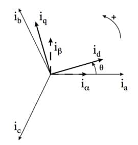
Field-oriented control translates electrical signals from the motor and incorporates them into the direct-quadrature coordinate model. This model is normally calculated relative to the rotor as this typically makes the calculations for desired flux easier. The calculations used to produce these transformations are mathematically intensive. One example is the pairing of the Clarke and Park transforms.
The Clarke transform method takes the three phase currents and uses them estimate currents in a Cartesian coordinate system, generally denoted as alpha and beta in motor-control equations rather than the conventional x and y. These are then taken by the Park transform to provide currents that can be applied in a direct-quadrature coordinate system.

Figure 2: The relationship between coordinate systems as used by field-oriented control methods.
The measured back-EMF can be used to estimate the rotor slip, although there is a computation cost with increasing accuracy. The more accurate the slip prediction the less energy will be wasted, making it a prime consideration for energy-efficient motors.
The magnitude of back‐EMF voltage is proportional to the rotor speed, which causes problems at low speeds or at standstill, where it is practically impossible to estimate the initial position. Therefore, starting from unknown rotor position may be accompanied by a temporary reverse rotation or may cause a starting failure. A further drawback with just sampling back-EMF is that the technique is sensitive to stator resistance, which is prone to change with temperature.
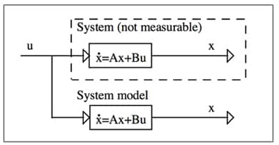
What is required is a method to calculate the state variables of interest without relying directly on measurements. Instead, a system model is used to estimate the real-time values of these variables based on the sensor readings that are possible. The problem with a basic system model is determining the starting point for the motor. One solution is to start with an estimate of the initial state from which a vector of predicted outputs can be derived, which is compared with the measured output vector. This difference is used to correct the internal state vector of the model. Basic correction methods do not fare well in the noisy environment of industrial motors. A more robust method is the Kalman filter, which caters for the effects of noise and sudden disturbances. However, the basic Kalman filter requires an understanding of the noise environment, which is difficult to generate for the changing environment of a running motor.
The extended Kalman filter uses matrices derived from the motor’s real-time behavior to adapt to the noise and make meaningful contributions to reducing the error between observed and predicted state. The Kalman filter algorithm relies on a number of matrix multiplications and inversions. The key to implementing the extended Kalman filter in motor control is therefore high arithmetic performance.

Figure 3: Use of a model to estimate the value of parameters that cannot be measured directly.
There is an alternative to field-oriented control. This is direct-torque control. Instead of using coordinate transforms and a current-based model to estimate flux angle, this technique applies two hysteresis comparators and a look-up table of switching states. This results in a relatively simple implementation. However, the variation in flux and torque can be large.
One option to overcome inaccuracies is to use space-vector pulse width modulation, using the measured current and voltage applied to a model of the motor, to derive an output voltage level. This is more mathematically complex as it relies on the ability to solve a system of quadratic equations in real time. The approach also has greater difficulty in dealing with changes in load than the field-oriented control strategy. However, the approach is viable for situations where this is unlikely to be a problem – and work continues on the algorithms to improve the accuracy of direct-torque control.
Although there are significant choices to be made in the types of algorithm that are used in motor control, a unifying aspect is the requirement for signal-processing performance. IC manufacturers have responded with an array of solutions, many of them filling the gap between digital signal processor (DSP) and conventional microcontroller, making it possible to run algorithms such as Kalman filters alongside PWM control and communications functions. These devices are optimized for the repeated multiplications and additions that form the basis of matrix operations. Basic Kalman filter-based control has been implemented for a number of years on DSPs with at least 20 MIPS of performance.¹ New architectures have extended the range of performance to accommodate more sophisticated control strategies and allow for multitasking or multiple motor control.
The digital signal controller (DSC) – a hybrid of DSP and general-purpose CPU – has become common in motor-control applications. An example of the DSC is Microchip Technology’s DSPIC33FJ, a 16-bit MCU with integrated DSP functions that runs at up to 70 MIPS. In common with many MCUs aimed at industrial control, the DSPIC has integrated hardware PWM support to take care of providing gate-control signals to the inverter section of a motor control board to ensure that accurate voltage levels are provided to each of the motor coils. Hardware PWM reduces the workload of the core CPU and reduces the number of interrupts to which the core has to respond within each rotation cycle, providing more bandwidth for arithmetic processing.
Other on-chip peripherals include high-resolution ADCs for capturing voltage and current signals, as well as analog comparators and a variety of communication peripherals for attachment to serial buses.
Freescale’s 56F800 DSC family uses a parallelized architecture to support motor-control and other real-time functions on a processor that runs at up to 100 MHz. The 56800 core is based on a dual Harvard architecture. The Harvard architecture is commonly used in DSPs rather than the von Neumann architecture of MCUs because of its higher data throughput. The Freescale dual-Harvard approach allows three execution units to operate in parallel, which are capable of more than one operation per cycle. As a result, as many as six operations per instruction cycle are possible on the 56800. However, to ease code development, the architecture employs an MCU-style programming model with an instruction set that was designed to be highly efficient for the code-generation modules of C compilers.
A device such as the 32 MHz MC56F8006 provides a six-channel hardware PWM to support three-phase power-stage control and forty general-purpose I/O lines, as well as two 28-channel 12-bit ADCs to support a large number of voltage, current, and sensor inputs.
Analog Devices’ Blackfin family of control-oriented DSPs is another example of the trend to integrate components such as high‐resolution ADCs for precise data conversion and modeling accuracy, together with on-chip flash memory to further speed algorithm processing. The approach minimizes off‐chip components with the aim of lowering overall system costs. The Blackfin is suited to systems that need sophisticated control strategies, providing clock speeds up to 400 MHz.
An alternative is to opt for dual-core processing such that DSP code can run on a dedicated processor while functions that better suit a traditional MCU run on a more general-purpose processor. Texas Instruments’ C2000/C28x architecture has been a viable target for motor-control code that includes algorithms such as Kalman filters for more than a decade. The company has continued to develop the DSP core at the heart of the C2000 family but add the ARM® Cortex™-M3 processor to its Concerto family.
The Cortex-M3 is intended primarily for communications, relaying real-time data on motor performance and other factors to servers over a network. As a result, the Concerto contains a wide variety of communication peripherals, including Ethernet 1588, USB OTG with integrated PHY and CAN as well as UART, SSI and I²C serial ports.
The C28x floating-point DSP core handles real-time control. Support for floating-point allows for easier prototyping with high-level control-algorithm tools, which generally output code that assumes the presence of floating- rather than fixed-point arithmetic. The core runs at up to 150 MHz and is supplemented by a number of acceleration units to further increase performance, particularly for functions that consume large amounts of CPU processing cycles, but are computationally relatively simple.
For motor control, the Concerto has an integrated extended PWM block with built-in fault protection, and supports inputs from encoders and other capture inputs. In addition, the C28-CPU has been enhanced with units for performing: complex arithmetic to assist with advanced transformation algorithms; fast Fourier transforms, which can be used to monitor engine health by monitoring sonic behavior for signs of excessive wear; as well as cyclic redundancy codes (CRC) to ensure that code and received data packets are valid.
If communications functions can be incorporated into the main real-time core, many single-processor versions of the C28x are also available, such as the 150 MHz TMS320F281x series. Using hybrid architectures and DSPs that are designed for real time operation, IC manufacturers have developed solutions that make feasible optimized control strategies for AC motors that will deliver on predictions for greatly improved energy efficiency.
References

免责声明:各个作者和/或论坛参与者在本网站发表的观点、看法和意见不代表 DigiKey 的观点、看法和意见,也不代表 DigiKey 官方政策。


