制造商零件编号 17720
SPARKFUN MICROMOD RP2040 PROCESS
SparkFun Electronics
License: See Original Project MicroMod Qwiic Raspberry Pi MCU
Courtesy of SparkFun
Guide by bboyho
Introduction
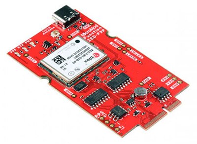
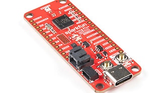
The MicroMod RP2040 Processor Board is a low-cost, high-performance board with flexible digital interfaces featuring the Raspberry Pi Foundation's RP2040 microcontroller. The board takes advantage of the MicroMod M.2 connector to easily swap out processor boards on carrier boards.
Required Materials
To follow along with this tutorial, you will need the following materials. You may not need everything though depending on what you have. Add it to your cart, read through the guide, and adjust the cart, as necessary.
Suggested Reading
If you aren't familiar with the MicroMod ecosystem, we recommend reading here for an overview. We recommend reading here for an overview if you decide to take advantage of the Qwiic connector.
If you aren’t familiar with the following concepts, we also recommend checking out these tutorials before continuing.
Serial Communication: Asynchronous serial communication concepts: packets, signal levels, baud rates, UARTs and more!
Serial Peripheral Interface (SPI): SPI is commonly used to connect microcontrollers to peripherals such as sensors, shift registers, and SD cards.
Pulse Width Modulation: An introduction to the concept of Pulse Width Modulation.
Logic Levels: Learn the difference between 3.3V and 5V devices and logic levels.
I2C: An introduction to I2C, one of the main embedded communications protocols in use today.
Analog vs. Digital: This tutorial covers the concept of analog and digital signals, as they relate to electronics.
Getting Started with MicroMod: Dive into the world of MicroMod - a compact interface to connect a microcontroller to various peripherals via the M.2 Connector!
Hardware Overview
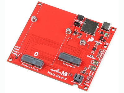
M.2 Connector
All of our MicroMod Processor Boards come equipped with the M.2 MicroMod Connector, which leverages the M.2 standard and specification to allow you to install your MicroMod Processor Board on your choice of carrier board. Most of the pins use a common pinout to ensure cross platform compatibility.
Note: While the MicroMod RP2040 Processor Board is designed to mate with M.2 Connectors that are populated on Carrier Boards, the RP2040 is not compatible specifically with the MicroMod Machine Learning Carrier Board.
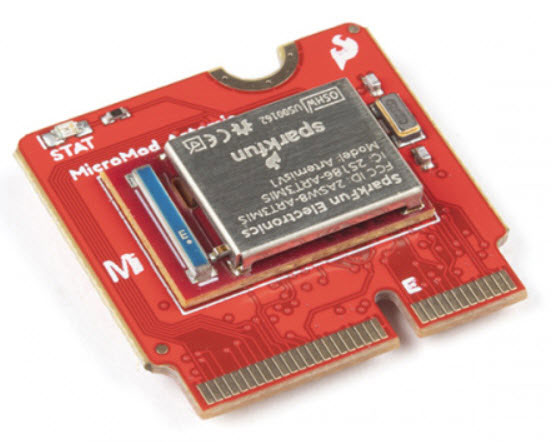
RP2040 Processor
The brains of the processor board is the Raspberry Pi Foundation's RP2040 ARM Cortex M0+ processor. An external 12MHz crystal is used as the clock for the RP2040. The RP2040 should be powered with 3.3V from a carrier board's M.2 connector. The logic levels for the I/O pins are 3.3V.
Flash Memory
On the back of the board is the W25Q128JVPIM, which adds 128Mb (16MB) of flash memory externally.
LED
A STAT LED is added to the top side of the board. This is useful debugging or as a status indicator. This is connected to GPIO25.
MicroMod RP2040 Processor Pin Functionality
The complete pin map can be found in the table below or you can refer to the schematic.
Heads up! The pin table below and schematic both include the RP2040 pin associated with each MicroMod pin, and this correlation can be used to identify alternate uses for pins on the RP2040 Processor Board. For many of the General Purpose I/O pins and other pins with multiple signal options, refer to your Carrier Board's Hookup Guide for information on how those pins are configured what they are used for. Not all pins are used on every Carrier Board.
Depending on your window size, you may need to use the horizontal scroll bar at the bottom of the table to view the additional pin functions. Note that the M.2 connector pins on opposing sides are offset from each other as indicated by the bottom pins where it says (Not Connected)*. There is no connection to pins that have a "-".
RP2040 Processor Pinout Table
MicroMod General Pinout Table
MicroMod General Pin Descriptions
Note: There is an additional ADC pin that is not broken out on the RP2040. It is connected to the internal temperature sensor. While it is not broken out on the board, you can access the temperature sensor readings using examples from either the C/C++ or MicroPython SDK.
Board Dimensions
The board takes advantage of the standard MicroMod form factor.
Hardware Assembly
If you have not already, make sure to check out the Getting Started with MicroMod: Hardware Hookup for information on inserting your Processor Board into your Carrier Board.
Dive into the world of MicroMod - a compact interface to connect a microcontroller to various peripherals via the M.2 Connector!
Note: While the MicroMod RP2040 Processor Board is designed to mate with M.2 Connectors that are populated on Carrier Boards, the RP2040 is not compatible specifically with the Machine Learning Carrier Board.
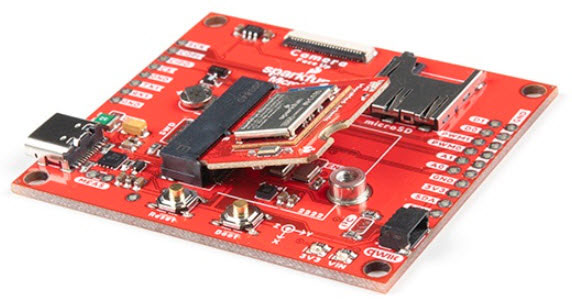
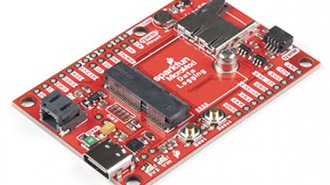
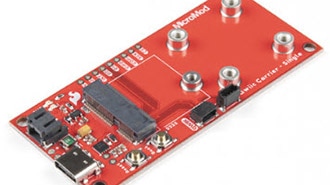
For simplicity, we'll be using the MicroMod ATP Carrier Board to program the board. At a minimum, your setup may look like the image below with the MicroMod RP2040 Processor Board.
To program, you'll need a computer, and a USB-C cable inserted into the MicroMod ATP Carrier Board. In this tutorial, we will use a Raspberry Pi.
Qwiic-Enabled Device
If you decide to use a Qwiic device (because why not?!), simply insert a Qwiic cable between the two connectors. Note that not all Qwiic enabled devices have a MicroPython driver yet.
UF2 Bootloader
The MicroMod RP2040 processor board is easy to program, thanks the UF2 bootloader. With this bootloader, the board shows up on your computer as a USB storage device without having to install drivers for Windows 10, Mac, and Linux!
What is UF2?
UF2 stands for USB Flashing Format, which was developed by Microsoft for PXT (now known as MakeCode) for flashing microcontrollers over the Mass Storage Class (MSC), just like a removable flash drive. The file format is unique, so unfortunately, you cannot simply drag and drop a compiled binary or hex file onto the board. Instead, the format of the file has extra information to tell the processor where the data goes, in addition to the data itself. For more information about UF2, you can read more from the MakeCode blog, as well as the UF2 file format specification.
Software
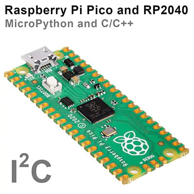
There are two methods of programming the RP2040. You can use MicroPython or C/C++ depending on your personal preference. The documentation is written for the Raspberry Pi's Pico development board but will apply for any board with the RP2040. Just make sure to adjust the pin definition depending on what GPIO is broken out.
Getting Started with the Raspberry Pi Pico
Stay tuned for more information!
MicroPython Examples
The Raspberry Pi foundation has provided the necessary tools, documentation, and examples to get started with the RP2040. If you haven't already, check out the documentation on the Pico. We'll use this as a reference when using the chip on other development boards to fit your needs in this tutorial.
Raspberry Pi: Pico Python SDK (PDF)
We'll be using the MicroPython examples from this GitHub repo using Thonny IDE.
GitHub: raspberrypi/pico-micropython-examples
Installing MicroPython on the RP2040
Note: Interested in going further? The Raspberry Pi Foundation also released a book to get started with the Pico's RP2040: "Get Started with MicroPython on Raspberry Pi Pico." While it is written for the RP2040, you can use it as a guide for any boards with the RP2040. Just make sure to
Get Started with MicroPython on Raspberry Pi Pico
To install MicroPython on the RP2040, you will need to download the firmware from Raspberry Pi. Click below to head to the Raspberry Pi Foundation's MicroPython UF2 File for the RP2040. Click on the tab for the "Getting started MicroPython" and the button for Download UF2 File.
Raspberry Pi Documentation: RP2040
On your MicroMod carrier board, find the boot and reset button. Press and hold the boot button down with one finger.
Press the reset button with momentarily with another finger.
Release the boot button. The board should appear on your computer as a removable drive called RPI-RP2.
Draw and drop the UF2 file into the "removable drive". The board will automatically reboot. Below is an image highlighting the UF2 file being moved to the removeable drive on a Raspberry Pi.
Configuring Thonny IDE
Note: If you are using a Raspberry Pi, make sure that you are using the latest Raspberry Pi image. Enter the following command in the LXTerminal to download and install the latest packages. The && combines the two commands into a single line and the -y answers "yes" to any prompts.
sudo apt update && sudo apt full-upgrade -y
Check to make sure that you are using Thonny v3.3.3 and above. If you are using a Raspberry Pi, type the following command to check the version:
thonny -v
You should get a result similar to the output below. If you have a version that is equal or higher, you should be good to go!
INFO thonny:Thonny version: 3.3.3
If you are using a different operating system, you can also download the Thonny IDE.
Open Thonny up from the start menu: Raspberry Pi Start Menu > Programming > Thonny Python IDE
Set Thonny's interpreter for the RP2040. The "Raspberry Pi Pico" will work for the RP2040. Head to the menu and select: Run > Select Interpreter....
This will open a new window for the Thonny options. In the Interpreter tab, select MicroPython (Raspberry Pi Pico) as the interpreter.
Note: You can also click on the bottom right to Configure Interpreter... and follow the same steps outlined above.
In the same window, make sure to select the option to have Thonny automatically detect the COM port for the board: Port > < Try to detect port automatically >
Note: If you are on Linux based OS like the Raspberry Pi, the COM port may show up as tty(AMA0 (/dev/ttyAMA0).
Hello World!
To check if this is working open the Thonny IDE, type the following into the editor. Feel free to adjust the message to whatever you prefer.
print("Hello world!")
Hit the "Run current script" button. In the Shell, you will see the following output. Sweet!
>>> %Run -c %EDITOR_CONTENT
Hello world!
Note: To save the file and have it run every time the board is powered up, simply select File > Save As... from the menu.
When a window pops up, select Raspberry Pi Pico.
Then save the file as main.py.
Just make sure to save any code that was edited on your computer (e.g., Save as... > This computer) before closing Thonny.
Warning: If you are using a terminal window and REPL, you will need to type the functions into the terminal window. While you can copy and paste, the terminal window will not recognize indents for loops or custom defined subroutines. As a result, the pasted code will not be interpreted correctly by REPL. You'll want to make sure that you are using the Thonny editor to avoid this error.
Blink
If you have the MicroPython examples saved, head to the following folder in your downloads .../pico-micropython-examples/blink/blink.py . Your code should look like the following. Of course, you can also copy and paste the code provided after the next paragraph as well.
# ========== DESCRIPTION==========
# The following code was originally written by
# the Raspberry Pi Foundation. You can find this
# example on GitHub.
#
#     https://github.com/raspberrypi/pico-micropython-examples/blob/master/blink/blink.py

from machine import Pin, Timer

led = Pin(25, Pin.OUT)
tim = Timer()
def tick(timer):
    global led
    led.toggle()

tim.init(freq=2.5, mode=Timer.PERIODIC, callback=tick)
Hit the "Run current script" button. Once the code runs, you will see the LED blink. If you want the board to run blink every time the board is powered up, just follow the note provided at the end the previous example.
Resources and Going Further
For more information, check out the resources below:
RP2040 Datasheet (PDF) (31.2 MB)
Raspberry Pi Pico Datasheet (PDF) (16.5MB) - An RP2040-based microcontroller board
Getting Started with Raspberry Pi Pico (PDF) (32.9MB) - C/C++ development with Raspberry Pi Pico and other RP2040-based microcontroller boards
Raspberry Pi Pico C/C++ SDK (PDF) (2.14MB) - Libraries and tools for C/C++ development on RP2040 microcontrollers
Raspberry Pi Pico Python SDK (PDF) (2.66MB) - A MicroPython environment for RP2040 microcontrollers