


Tough Driver Requirements Push Designers Toward New Power IC Technologies
投稿人:DigiKey 北美编辑
2016-07-27
Semiconductor driver technologies like FETs (MOSFETs, HEMTs) and IGBTs (insulated-gate bipolar transistors) are doing well when it comes to providing more bang for the buck, but they are struggling to keep up with increasing performance demands of the wide bandgap (WBG) power semiconductor ICs – like GaN and SiC – that are replacing silicon MOSFETs as power ICs.
The demands include lower switching losses, greater noise immunity, shorter propagation delays, and higher voltage and current capabilities at higher switching frequencies. Dealing with all these, within tighter form factors, is becoming a major challenge for driver device providers.
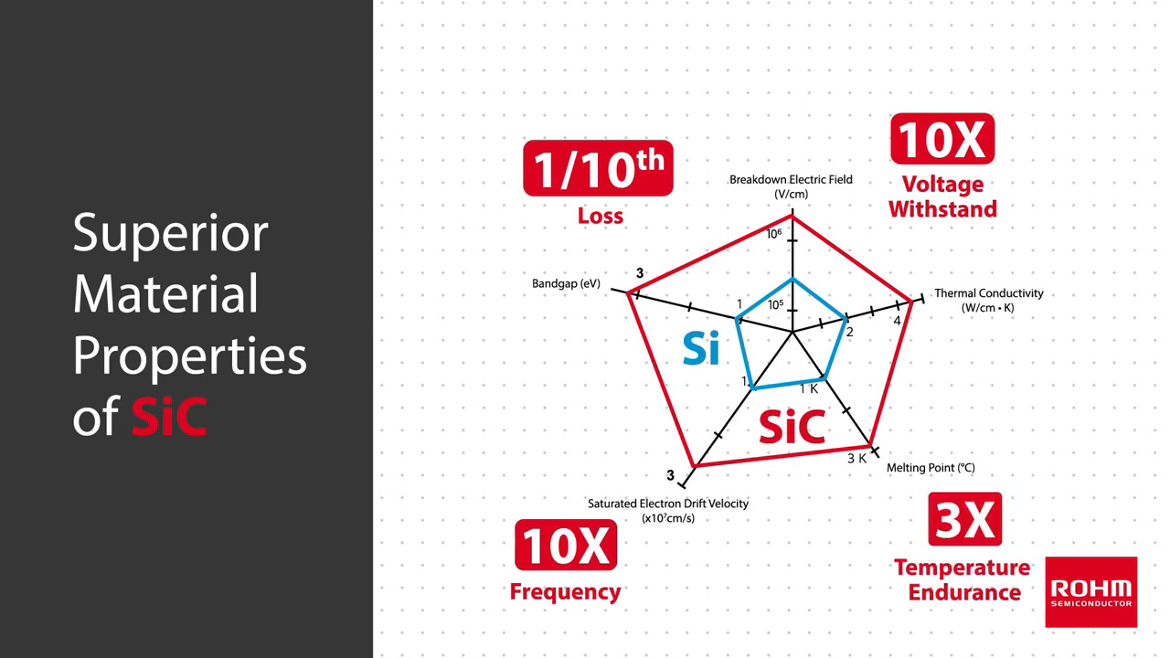
The latest generation of 600 V and 650 V MOSFETs have come a long way in satisfying increasing demands of switch-mode power supply (SMPS), uninterruptable power supply (UPS), motor drive, inverter, converter, induction heating, wind-power, and photovoltaic systems. However, it’s getting difficult to satisfy the increasing demands of these applications. WBG semiconductor devices based on GaN and SiC technologies appear to be the answer to answering those driver demands.
Switching frequencies of 20 kHz are common for IGBTs and MOSFETs. However, there are newer WBG drivers that offer higher performance levels, but at what price?
A major performance consideration is a MOSFET’s gate capacitance, which may not be much of a problem for low-frequency switching applications. However in higher-speed switching applications, the MOSFET’s gate must switch between high or low quickly, with sufficient current, so that the MOSFET spends a minimal amount of time in the linear region.
Getting the best performance out of GaN and SiC devices involves designing the power circuit within an existing pc-board (PCB) layout system that was originally designed for a MOSFET, one that takes full advantage of the performance gains offered by these newer ICs. All of this must be met while meeting cost, form-factor (i.e. package size) and budget constraints.
The latest generation of 600 V and 650 V GaN MOSFETs, for example, can handle higher breakdown voltages well above those of their rated steady-state voltages than the most advanced MOSFETs. SiC devices can handle substantially higher voltages and currents.
With faster edge rates, GaN power ICs allow designers to significantly increase switching frequencies, minimizing parasitic inductance and capacitance effects associated with higher switching rates. Also, SiC power ICs offer even higher performance levels, though at a slightly higher cost than silicon MOSFETs.
When laying out the driver and FET on a PCB, care must be taken to keep them as close as possible to minimize losses induced by capacitance and inductance effects. Ultimately, technology has to progress to the point of monolithic integration, where a power semiconductor driver and the FET switch can be put on the same silicon wafer.
A closer look at drivers
Isolated-gate MOSFET and IGBT gate drivers can be setup as with split outputs to suit many industrial and medical applications that require both positive and negative supply voltages to operate. Normally, such circuits require ±5 V, ±12 V, ±15 V, or higher voltages. However, while positive voltages are common on a typical PCB, generating negative voltage becomes challenging when the power required is more than 1 W and the supply must be isolated.
One parameter, common-mode transient immunity (CMTI), specified in kV/µs, is beginning to appear in power device characterization. Until now, it has been the purview of isolator manufacturers’ data sheets.
Texas Instruments solved the CMTI issue with its ISO5452 2.5 A / 5 A isolated-gate driver for IGBTs and MOSFETs with split outputs and active safety features (Figure 1).

Figure 1: Isolated MOSFET gate drivers, like the Texas Instruments ISO5452, allow fast switching of high voltages with good common-mode transient immunity (CMTI). (Image courtesy of Texas Instruments)
The device features 2.5 A / 5 A split outputs to provide 2.5 A peak source currents and 5 A peak currents, and provides a slew rate of 50 kV/µs (at Vcm of 1500 V) typical. It has a short propagation delay of 76 ns (110 ns maximum), a 2 A active Miller clamp, as well an output short-circuit clamp (Figure 2).

Figure 2: Texas Instruments’ IS05452 isolated MOSFET and IGBT driver has both a unipolar (left) and bipolar (right) output supply. A 0.1 µF bypass capacitor is recommended at input supply pin VCC1, and a 1 µF bypass capacitor at output supply pin VCC2 provide the large transient currents necessary during a switching transition. (Image courtesy of Texas Instruments)
A typical motor-drive three-phase inverter application using six TI ISO5452 gate drivers can be used for variable-frequency drives to control the operating speed of AC motors and for high-power high-voltage DC power transmission.
The basic three-phase inverter consists of three single-phase inverter switches each comprising two TI ISO5452 devices that are connected to one of the three load terminals (Figure 3). The operation of the three switches is coordinated so that one switch operates at each 60-degree point of the fundamental output waveform, thus creating a six-step line-to-line output waveform. In this type of application, carrier-based pulse-width modulation (PWM) techniques are applied to retain the waveform envelope and cancel harmonics.

Figure 3: A typical application for a three-phase inverter motor drive using six TI ISO5452 gate drivers. (Image courtesy of Texas Instruments)
ON Semiconductor offers the NPC81074A/B single-channel 10 A high-speed low-side MOSFET driver that’s capable of providing large peak currents into capacitive loads (Figure 4). It features high current-drive capability of ±10 A, 10 A peak reverse-current capability, 4 ns typical rise and fall times with a 1.8 nF load, and 15 ns input rise and fall times. The device’s split-output configuration and a dual input design offer drive flexibility. Its TTL/CMOS-compatible inputs are independent of the supply voltage of 4.5 to 20 V.

Figure 4: A typical application layout for the ON Semiconductor NCP81074A/B single-channel 10-A high-speed low-side MOSFET. It is extremely important to keep the driver and the MOSFET being driven as close as possible for high-current fast-switching applications. ON Semiconductor goes so far as to recommend a specific layout. (Image courtesy of ON Semiconductor)
ROHM Semiconductor made an important breakthrough with the BSM300D12P2E001, a hybrid that combines both the SiC MOSFET and a Schottky barrier diode in one small package (Figure 5). It also includes a built-in NTC thermistor for 175°C maximum junction temperature protection.

Figure 5: The BSM300D12P2E001 hybrid SiC module from ROHM Semiconductor includes a Schottky barrier diode in a package size equivalent to a standard IGBT module (62 mm wide in an E type package) to handle 1200 V and 300 A. (Image courtesy of ROHM Semiconductor)
It features a 77% lower switching loss than an IGBT module (switching loss is about 19 mJ), operates from -6 to 22 V, has an RDS(ON) of just 7.3 Ω, and functions over the temperature range of -40°C to 175°C. It can also handle a 2500 VAC isolation voltage for 1 minute.
Key to the product’s realization is ROHM’s use of an original electric field migration structure along with a novel screening method (Figure 6).

Figure 6: ROHM Semiconductor’s BSM300D12P2E001 SiC power module uses an original electric field migration structure along with a novel screening method to pack a SiC Schottky barrier diode, a MOSFET, and an NTC thermistor in a package size equivalent to a standard IGBT module. (Image courtesy ROHM Semiconductor)
Conclusion
The requirements that GaN and SiC power devices place upon their drivers means that, ultimately, hybrid and monolithic integration of the driver and power IC circuitry may be the answer. Cognizant of this, GaN and SiC manufacturers are working on the monolithic approach. Since growing GaN MOSFETs with a driver on a silicon wafer is within reach, and the costs are coming down, expect to see monolithic GaN MOSFETs soon at reasonable costs.
Growing SiC on silicon wafers is more difficult and more costly. Still, its performance capabilities are well beyond those of GaN and it is projected to fulfill niche application requirements other technologies cannot meet.
免责声明:各个作者和/或论坛参与者在本网站发表的观点、看法和意见不代表 DigiKey 的观点、看法和意见,也不代表 DigiKey 官方政策。


 中国
中国