


Power Management Tips for Energy Harvesting Systems
投稿人:DigiKey 欧洲编辑
2015-12-08
Designing a power management system for a source that harvests energy from the environment can be challenging. These sources, from solar cells to vibrational energy, and even power from thermal differences, are all small amounts of power that vary unpredictably. This creates a significant challenge for a power management system that has to run efficiently and provide a steady output. The voltage and power requirements of the sensors and processors in the node being powered have dropped, so using an energy harvesting source has become more practical; but there are still different ways to manage these power sub-systems.
It is obviously necessary to optimize the design for the low average power in the system, but it is also necessary to understand the lower and upper limits of the energy harvesting source. A buck/boost converter will have a lower limit below which the power stage may either shut down or not start, interrupting the operation of the system. This also means the power up sequencing must understand implications of when to power each device along with other devices so that the power drain does not push the power conversion stage below that lower limit.
However, it is also necessary to be aware of the potential peak power to avoid overwhelming the additional energy storage element such as a capacitor or battery.
Using hardware timers and interrupts rather than software reduces the overall power requirement, and having status indications and alerts implemented across the systems are essential so that power management choices can be made with the right information.
Isolating all the loads in the system and making them switchable gives the power manager more opportunities to avoid problems and optimize the performance. This also helps isolate any devices that are consuming too much power.
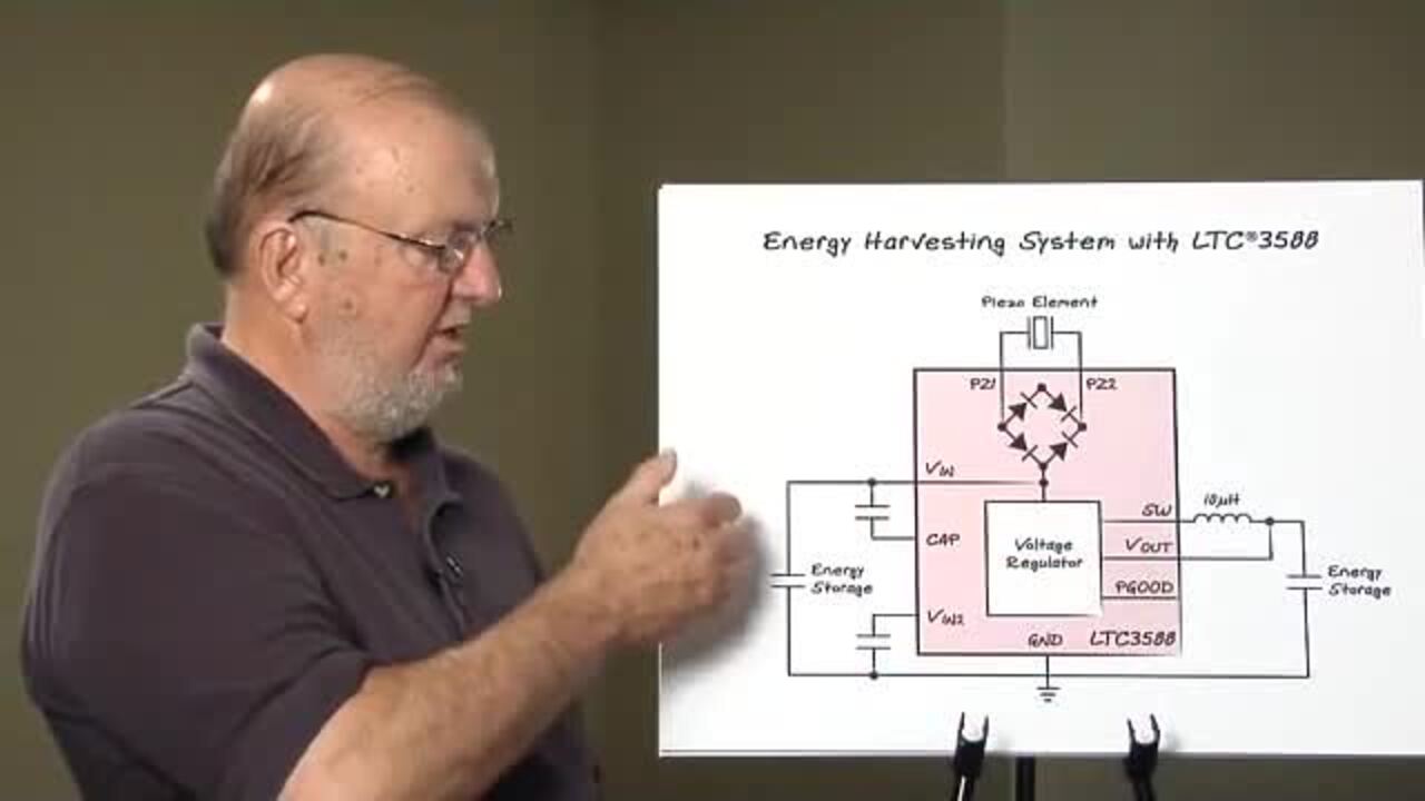
A buck/boost converter is a suitable architecture for harvesting energy from movement or vibration via a piezoelectric transducer. A protective shunt at the input allows the power manager to accommodate a variety of different piezoelectric elements, which can have short-circuit currents around 10 µA.
An example of a typical power manager for a piezoelectric source is the LTC3588 from Linear Technology. This is designed to interface directly to a piezoelectric or alternative power source, rectify a voltage waveform and store the harvested energy on an external capacitor, as well as bleed off any excess power via an internal shunt regulator.
It integrates a low-loss full-wave bridge rectifier with a high efficiency buck converter that is optimized for high output impedance piezoelectric sources, and maintains a regulated output voltage with a high efficiency synchronous buck regulator.
An ultralow quiescent current undervoltage lockout (UVLO) mode with a wide hysteresis window allows charge to accumulate on an input capacitor until the buck converter can efficiently transfer a portion of the stored charge to the output, and the buck converter turns on and off as needed to maintain regulation.
An example of the importance of knowing the lower limit comes with the buck converter, which starts when the input voltage moves above the UVLO rising threshold to transfer charge from the input capacitor to the output capacitor. The 1 V UVLO hysteresis window has a lower threshold of around 300 mV above the selected regulated output voltage, and this prevents short cycling during the buck power-up.
When the input capacitor voltage is depleted below the UVLO falling threshold, the buck converter is disabled and the extremely low quiescent current of 450 nA allows energy to accumulate on the input capacitor from the piezoelectric source. The hysteresis is determined by an algorithm that controls the output through internal feedback from the voltage sense pin.

Figure 1: The quiescent current undervoltage lockout (UVLO) uses a hysteresis algorithm to protect the power delivery in a piezoelectric energy harvesting system.
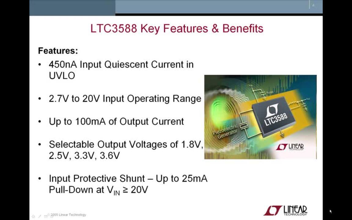
The four output voltages in the LTC3588 show the lower voltages that the energy harvesting source is expected to power, from 1.8 V, 2.5 V and 3.3 V to 3.6 V, and these are pin selectable with up to 100 mA of continuous output current. An input protective shunt set at 20 V enables greater energy storage for a given amount of input capacitance.
The low-loss bridge rectifier has a total drop of about 400 mV, with typical piezo generated currents of around 10 µA, and the bridge is capable of carrying up to 50 mA. All of this allows the charge in the capacitor to smooth out the intermittent nature of the source of power and provide the required voltage to the sensor or controller.
Batteries are often used to collect the charge from the energy source, but these also need to be protected from overcharging or undercharging. The MAX17710 from Maxim Integrated can manage the poorly regulated energy harvesting sources with output levels ranging from 1 µW to 100 mW. For a 0.8 V harvest source and a 4.1 V cell, the device can deliver over 20 mA (80 mW) for as long as the harvest source can support it.
To do this, the device includes a boost regulator circuit for charging a lithium battery from a source as low as 0.75 V, while an internal regulator to protect the cell from overcharging and an internal voltage protection prevents the cell from over discharging. The selectable output voltages from 1.8 V through 2.3 V to 3.3 V are regulated using a low-dropout (LDO) linear regulator.

Figure 2: The MAX17710 integrates a low-dropout regulator to protect a capacitor or lithium battery cell from undercharging.
Solar power
An increasingly popular source for energy harvesting is a solar cell, and there are several different ways to manage the power coming from such cells. These different approaches are freely available through digital libraries, and can be tested out on a range of evaluation boards.
The digital power software libraries for solar cells provide code-optimized building blocks to implement a variety of power topologies and algorithms such as maximum power point tracking (MPPT) and Software Phase Locked Loops (PLL) to help design optimized solar inverters to power equipment.
There are three basic MPPT algorithms that can be easily tested out in a microcontroller. The most popular is the perturbation and observation (P&O) algorithm, also called the ‘hill climbing method’, where the controller moves, or perturbs, the voltage coming from the array by a small amount and measures power. If the power increases, the voltage is changed a little more in the same direction until the maximum power point is reached. However, this can result in oscillations of power output around a point.
")
Figure 3a: The basic P&O algorithm (Source: MATHWORKS)
The second option, Incremental Conductance, compares the incremental conductance to the instantaneous conductance. Depending on the result, it increases or decreases the voltage until the maximum power point (MPP) is reached. Unlike with the P&O algorithm, the voltage remains constant once the MPP is reached.
")
Figure 3b: The incremental conductance algorithm. (Source: MATHWORKS)
A third MPPT approach is the fractional open-circuit voltage: This algorithm is based on the principle that the maximum power point voltage is always a constant fraction of the open circuit voltage. The open circuit voltage of the cells in the solar cell is measured and used as an input to the controller.

Figure 4: The Solar Micro Inverter development kit from Texas Instruments allows digital libraries of MPPT algorithms to be evaluated.
These power management algorithms can be tested out on the Solar Micro Inverter development kit from Texas Instruments, which is based on the Piccolo TMS320F28035 microcontroller and serves as a complete grid-tied solar micro inverter. The topology of the micro inverter consists of an active clamp fly-back DC/DC converter with secondary voltage multiplier, maximum power point tracking (MPPT), and a grid-tied DC/AC inverter. The single Piccolo controller handles both power stages and the execution of the MPPT algorithms.
Other evaluation boards, such as the MAX17710, allow the different topologies and algorithms to be tested, varying the energy storage elements and the control algorithms.

Figure 5: The MAX17710 evaluation board allows developers to charge a protected lithium battery cell from an energy source such as a solar cell.
Conclusion
Operating at the ultralow power levels of an energy harvesting source brings a number of challenges to the power systems developer. Keeping a close eye on the lower and upper limits of the energy source make the system design significantly easier. Developers can also evaluate the different control algorithms and tweak them to provide the most efficient power conversion for the chosen energy source, whether that is an array of solar cells, a piezoelectric vibration transducer, or a thermal energy source. These can be easily tested out, alongside the right choice of a battery cell or a capacitor, with a choice of evaluation boards.
免责声明:各个作者和/或论坛参与者在本网站发表的观点、看法和意见不代表 DigiKey 的观点、看法和意见,也不代表 DigiKey 官方政策。


 中国
中国