Quickly Build a Clinical-Grade Cardio Fitness Wearable with Minimal Parts Count
投稿人:DigiKey 北美编辑
2018-02-14
The demand for products able to deliver more comprehensive clinical-grade data from personal health monitoring devices presents significant challenges in the areas of sensor data acquisition, signal conditioning, and processing. However, developers now have available to them near drop-in hardware and software solutions that provide a flexible foundation for rapid implementation of clinical-grade products capable of a wide range of advanced physiological measurements.
This article will introduce one such solution from Maxim Integrated and discuss how to use it to address advanced fitness and wellness measurement challenges.
Health monitoring and prediction
Non-invasive wellness and health monitoring and prediction capabilities have emerged as key requirements for a growing range of products in both consumer and medical arenas. In creating these capabilities, developers depend on a rich set of data representing different physiological processes generated through a number of proven methods. Basic data such as heart rate provides important information on the individual’s physical condition, ability to recover from physiological stress, and other results.
Deeper insight on arterial oxygen saturation, respiration rates, and cardio response are critical not only for diagnosis in a clinical setting but also for physical training and extended wellness in a broader fitness context.
Measurement methods
Despite their nascent application in more mainstream products, the methods used to measure these characteristics have been in use for decades in acute observations and long-term clinical care. For basic heart rate measurement, optical plethysmography takes advantage of changes in light absorption or reflection associated with increases or decreases in the volume of blood passing through skin blood vessels with each heartbeat. Pulse oximetry estimates peripheral oxygen saturation (SpO2) by comparing light absorption or reflection at two different wavelengths selective for oxygenated hemoglobin (oxyhemoglobin) and deoxygenated hemoglobin (deoxyhemoglobin). Oxyhemoglobin absorbs more light than deoxyhemoglobin at infrared (IR) wavelengths around 940 nanometers (nm), and deoxyhemoglobin absorbs more light than oxyhemoglobin at visible wavelengths around 660 nm. Consequently, comparison of the received light at each wavelength provides SpO2 in peripheral blood vessels.
Rising interest in more detailed and comprehensive health data continues to drive a need for more sophisticated measurements. Among these, biopotential measurements use voltage sensing electrodes to trace voltage changes associated with heart action to generate an electrocardiogram (ECG) or associated with other muscle fibers to generate an electromyogram (EMG). For measuring cardiac health, the nature of the P, QRS, and T complexes in an electrocardiogram (ECG) can provide an extensive array of information (Figure 1).

Figure 1: ECGs provide extensive information about cardiac health based on amplitude, shape, and waveform timing. (Image source: FirstAidForFee.com)
At a minimum, the time between one R wave to the next (called R-to-R measurement) provides an instantaneous measure of heart rate. Experienced clinicians can discern detailed information about cardiac health and pathologies by examining the shape and amplitude of each waveform as well as the variation in timing between waveforms.
Perhaps less familiar, bioimpedance measurements take advantage of changes in impedance associated with changes in the underlying tissues and organs. During respiration, for example, changes in the amount of air in the lungs translate to changes in bioimpedance, providing a simple but reliable approach for measuring respiration rate and relative amplitude. Health experts are employing bioimpedance measurement in applications as varied as blood glucose detection, pneumonia detection, joint health assessment, and even heart failure prediction.
How developers go about building systems able to make these measurements remains a significant challenge. Few development teams have the technical expertise to create the kind of specialized matched signal chains required to extract data reliably and safely. Even for more experienced bioengineers, the time required to create custom data acquisition systems at best delays implementation of the applications required to deliver more sophisticated health and fitness monitoring products.
Developers can find that even seemingly straightforward techniques such as optical plethysmography and pulse oximetry present unexpected challenges. In theory, a simple heart rate monitor should require only a single light source to perform basic optical plethysmography, while a pulse oximeter should require only two light sources at wavelengths suitable for oxyhemoglobin and deoxyhemoglobin. In practice, however, different wavelengths of light reach different depths in epidermal and dermal layers and show different absorption or reflection characteristics to other molecules in blood and interstitial fluids. Consequently, the light returned at two wavelengths could be just as influenced by the penetration of each wavelength as the physiological phenomena each wavelength is meant to measure.
Developers often find the need to use multiple light sources not only to mitigate these effects, but also provide even more sophisticated measurements of vital statistics such as blood pressure. Combined with these specific concerns, more general requirements for low-power consumption and ease of use present designers with a complex set of challenges. The Maxim Integrated MAX86140 is designed specifically to provide a drop-in solution able to meet requirements for optical plethysmography and pulse oximetry applications.
Optical sensing solution
Designed for fitness and health applications, the MAX86140 is particularly well suited to small portable applications such as wearables. The 20-pin wafer-level package measures only about 2.0 x 1.8 millimeters (mm) and operates off a 1.8 volt main supply voltage, and a 3.1 to 5.5 volt LED driver supply voltage. At its maximum sample rate of 4,096 samples per second (sps), the device consumes about 660 microamps (µA), but developers can reduce sample rate to reduce power consumption. For example, at 25 sps, the device consumes only about 8.5 µA.
The device provides multiple features designed to reduce power consumption. For applications that require sample rates of 256 sps and below, developers can place the device in its dynamic power down mode. In this mode, the device automatically enters low-power mode between samples. Regardless of sample rate, developers can also take advantage of the device’s optical proximity function to save power when the device is removed from the user. Here, the device responds to reduced optical input levels by dropping its sample rate to 8 sps and entering dynamic power mode. When optical input rises above a set threshold, indicating close proximity of the user’s skin, the device resumes normal operation at the desired sample rate.
Beyond its power-saving features, the device provides a complete optical sensing system, combining a sophisticated optical receiver and LED driving control subsystem to deliver optical measurements. On the receiver side, the MAX86140 optical subsystem includes the full complement of functional blocks required for optical measurement (Figure 2). These blocks include ambient light cancellation (ALC), a sigma-delta analog-to-digital converter (ADC), voltage reference, temperature sensor with dedicated ADC, and a proprietary discrete time filter to reject 50 Hz/60 Hz interference.

Figure 2: The Maxim Integrated MAX86140 receiver integrates a complete signal chain with specialized blocks designed to optimize optical sensing in the presence of ambient light and noise sources. (Image source: Maxim Integrated)
Among its features, the ALC incorporates a proprietary mechanism for canceling ambient light, providing accurate results even in brightly lit environments. The device can even accommodate steep transient shifts in light that might occur as the user passes from a dark room to sunlight and back. The device’s “picket fence” capability allows it to replace an individual sample that exhibits a very large deviation from the norm with a value created by extrapolating sample history.
On the transmitter side, the MAX86140 integrates three programmable LED drivers that can be configured to drive a total of six LEDs. Powered by the separate LED driver supply, each LED driver channel comprises a digital-to-analog converter (DAC) and a current source capable of driving LEDs directly from the MAX86140’s LEDx_DRV output pins. To balance required accuracy and power consumption, developers can program each LED channel’s pulse width from 14.8 microseconds (µs) to 117.3 μs and set specific current output levels in four distinct ranges from 31 mA to 124 mA (Figure 3).

Figure 3: Developers can finely tune each MAX86140 LED current output level by setting LEDx_RGE[1:0] to the desired full-scale range and LEDx_PA[7:0] to the specific current output. (Image source: Maxim Integrated)
To perform a sampling sequence, developers can program the MAX86140’s integrated optical controller to drive one or more of its three LED driver channels simultaneously or sequentially (Figure 4). For optical plethysmography measurements in heart rate monitoring, developers would typically drive LEDs simultaneously to maximize optical return. For pulse oximetry, they would sequentially drive separate IR and red LEDs for measuring the ratio of oxyhemoglobin and deoxyhemoglobin needed to determine SpO2. Developers can also configure the controller to measure ambient light after each LED drive sequence to compensate for interfering ambient sources.

Figure 4: Developers can program the Maxim Integrated MAX86140 to drive separate LEDs simultaneously (A) for heart rate measurement or sequentially (B) for pulse oximetry, using a separate ambient measurement to compensate for interfering light sources. (Image source: Maxim Integrated)
Along with multiple configuration and control registers, the device provides a 128 word FIFO and pointers to the next word to be read or written. While sampling, the FIFO stores each sample sequentially, using a word comprising a 19-bit data value and a 5-bit tag that identifies the nature of the data. If more than one LED is used, the FIFO data stores each LED sample (and identifying tag) in sequential FIFO locations for a single sampling event. To read samples, developers need only access the FIFO data counter at address 0x07 to find the number of samples available in the FIFO, and then access the FIFO read pointer at 0x05 to read that number of samples. This simple approach allows developers to use correspondingly simple software routines to extract data quickly and efficiently (Listing 1).
void device_data_read(void) {
uint8_t sampleCnt;
uint8_t regVal;
uint8_t dataBuf[128*2*3];
int led1[32];
int led2[32];
ReadReg(0x07, &sampleCnt); //128 FIFO samples, 2 channel, 3 byte/channel
//Read FIFO
ReadFifo(dataBuf, sampleCnt * 3);
int i = 0;
for ( i = 0; i < sampleCnt; i++ ) {
led1[i] = ((dataBuf[i*6+0] << 16 ) | (dataBuf[i*6+1] << 8) | (dataBuf[i*6+2])) & 0x7ffff;
led2[i] = ((dataBuf[i*6+3] << 16 ) | (dataBuf[i*6+4] << 8) | (dataBuf[i*6+5])) & 0x7ffff;
} }
Listing 1: As illustrated in this pseudo-code, developers need only a few operations to read available samples from the Maxim Integrated MAX86140’s on-chip FIFO. (List source: Maxim Integrated)
Unlike a typical event-driven system, MAX86140 FIFO data does not include explicit timestamps. Instead, the FIFO fills at the specified sample rate, allowing developers to easily recreate the event timestamp associated with a sample. Nevertheless, developers who need to synchronize device measurements with other measurements can program the device to periodically include a timestamp in the FIFO. The device itself includes dedicated ports (GPIO1 and GPIO2) that can be used to control other devices. In a typical MCU-based application, however, the device requires few connections or additional components to implement optical sensing (Figure 5). Along with serial connections to the host processor, developers add a photodiode such as the Vishay Semiconductor VEMD5010X01 and one or more LEDs with wavelengths appropriate to the specific application.

Figure 5: Because the Maxim Integrated MAX86140 integrates a complete optical sensing solution, developers need only a few additional components to implement a heart rate and pulse oximetry design. (Image source: Maxim Integrated)
To help developers build their own MAX86140-based designs, Maxim Integrated provides the MAX86140EVSYS evaluation kit and an associated Windows® program. The MAX86140EVSYS offers a comprehensive development platform for rapid development and evaluation, providing schematics and hardware implementation of the design illustrated in Figure 5. Along with a fully implemented MAX86140-based optical sensing system, the evaluation kit includes a main data acquisition board built around the Maxim Integrated MAX32620 32-bit Arm® Cortex®-M4F-based MCU.
To help developers evaluate the operation of the device’s large number of configuration and operating options, the Windows program provides developers with a simple tool for changing options and observing the results (Figure 6). After confirming the optimal operating configuration, developers would simply apply the same values to their own code to use the MAX86140 in their own designs.
")
Figure 6: Developers can use a Maxim Integrated Windows software program to test specific device settings and evaluate the impact of those settings on device performance and optical measurement results. (Image source: Maxim Integrated)
Detailed health data
Although the MAX86140 can provide a wealth of data with its optical sensing features, developers need to turn to biopotential and bioimpedance methods to provide ECG, respiration data, and other parameters mentioned earlier. In the past, developers faced a wide range of challenges associated with electrical signal acquisition in health and fitness applications. The combination of low-voltage biological signals and subtle changes in impedance associated with physiological processes required a high degree of expertise in building signal chains able to extract useful data. The Maxim Integrated MAX30001 provides a largely drop-in solution that meets the diverse requirements associated with these measurement methods.
For biopotential measurements such as ECG, the MAX30001 provides a dedicated channel that provides an optimized signal chain for reliable signal acquisition, conditioning, and conversion (Figure 7). Working in combination with a separate PACE channel for detecting pacemaker activity, the ECG channel can deliver full ECG waveforms, R-to-R heart rate data, and pacemaker event detection.
")
Figure 7: The Maxim Integrated MAX30001 integrates a dedicated channel for measuring biopotential signals used to generate the waveforms displayed in a typical ECG. (Image source: Maxim Integrated)
Although an ECG signal chain is complex in its own right, developers face a number of requirements for ensuring safe and reliable connection to the human user. The MAX30001 specifically addresses critical operating concerns through a multi-stage input subsystem that implements important features such as lead-on and lead-off checking, polarity setting, bias, and ESD protection (Figure 8).
")
Figure 8: At the input of the biopotential channel, a dedicated set of circuits provides critical protection, detection and calibration features essential for safe and reliable operation. (Image source: Maxim Integrated)
Here, integrated features such as input switches isolate the user from the internal signal path, protecting both user and sensitive internal circuits from transients that might occur while placing a chest strap, for example, that contains the external electrodes used for biopotential signal acquisition. In addition, the input system provides calibration voltages used as part of the device’s extensive self-test features.
Along with similar requirements for signal acquisition, conditioning, and conversion, bioimpedance measurements require the ability to generate small currents needed to detect changes in bioimpedance. The MAX30001 meets these requirements with a separate dedicated bioimpedance channel that combines an input signal chain with a current generator (Figure 9). The built-in programmable current generator produces a square wave current that is applied to the user’s body through pins DRVP and DRVN and used to sense bioimpedance through pins BIP and BIN.
")
Figure 9: Along with its dedicated input stage and signal chain, the Maxim Integrated MAX30001 bioimpedance channel includes a programmable current generator needed to measure changes in bioimpedance. (Image source: Maxim Integrated)
On the input side, developers need only add a few passive components to connect the device to two or four physical electrodes for both biopotential and bioimpedance measurements (Figure 10). Developers can further reduce parts count by using a device such as the Maxim Integrated MAX30034 for optional (but recommended) defibrillation protection.

Figure 10: Developers can easily implement four electrode input configurations able to support simultaneous biopotential and bioimpedance measurements using the Maxim Integrated MAX30001. (Image source: Maxim Integrated)
Designed specifically to absorb repetitive high energy pulses generated during defibrillation, the MAX30034 rapidly clamps voltage across its terminals, rapidly dropping from well over 1010 Ω to less than 1 Ω when positive or negative voltage levels exceed its trigger voltage.
The MAX30001 stores samples in a circular FIFO buffer in much the same way as the MAX86140. Sequential samples are placed in sequential FIFO locations, eliminating the need for separate timestamp data while allowing developers to reconstruct the time base. The MAX30001 does provide separate FIFOs for biopotential and bioimpedance samples, and also provides a single output register for R-to-R heart-rate data. As with the MAX86140, the MAX30001 fills each FIFO location with the data value and associated tag, which provides status information about each sample.
Implementation of a monitoring system based on the MAX30001 requires few additional components beyond the input protection network illustrated in Figure 10. Maxim Integrated demonstrates a basic configuration of the device with its MAX30001EVSYS evaluation system, which includes a MAX30001 evaluation board and a MAX32630FTHR board built around a Maxim Integrated MAX32630 Arm® Cortex®-M4F-based MCU.
By providing all the circuitry required for biopotential, bioimpedance, and pace detection, the MAX30001 largely eliminates the challenges associated with detailed hardware design. On the other hand, developers can find themselves spending time attempting to find the optimal combination of settings for the device’s very large number of configuration and operating options.
As with the MAX86140, Maxim Integrated provides developers with a Windows program that provides an intuitive graphics-based approach to configuration. Using separate tabs, developers can examine valid options for individual settings of individual components of each channel, apply a desired set of values, and immediately view plots showing results generated using those settings (Figure 11). After determining the optimal settings for their application, developers can simply apply those setting values for initialization and operation of the MAX30001 in their own application.
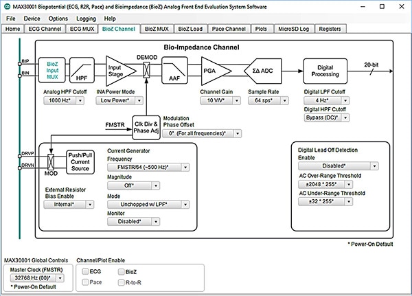
Figure 11: Maxim Integrated MAX30001 evaluation software lets developers select a tab corresponding to a particular device channel, set operating parameters for different stages in that channel, and view the results in a separate tab. (Image source: Maxim Integrated)
Conclusion
In creating next-generation wellness products, developers face diverse challenges in performing the series of measurements required to meet emerging demands for detailed, clinical-grade physiological data. As shown, the MAX86140 and MAX30001 from Maxim Integrated provide near drop-in solutions able to perform these measurements using well-accepted techniques for optical sensing, biopotential, and bioimpedance methods.
Using these devices and their associated evaluation kits, developers can rapidly design and implement sophisticated products capable of delivering clinical-grade wellness information.
免责声明:各个作者和/或论坛参与者在本网站发表的观点、看法和意见不代表 DigiKey 的观点、看法和意见,也不代表 DigiKey 官方政策。