Power for Motion Control
投稿人:DigiKey 欧洲编辑
2013-03-05
Motion-control systems used in automation are making use of more advanced control strategies and higher-frequency switching to provide higher-precision movement with lower energy demands. However, these advanced closed-loop control techniques have created new demands for the power components that deliver energy in precise charge packets to the motor windings. This article surveys developments in power MOSFETs and IGBTs to address these demands. Devices discussed will include products from Infineon Technologies (IKD03N60RF), International Rectifier (IRGB4060), STMicroelectronics (STGD3HF60HD), and Vishay Siliconix (IRFP460APBF).

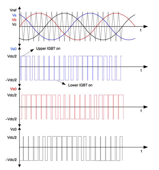
Figure 1: High frequency PWM switching provides clean changing voltage profiles to motor windings.
Energy efficiency has become a key concern in motor and motor drive design. Advanced control strategies and high frequency switching make it possible to combine precision movement with lower energy demands. However, these advanced control techniques are placing high demands on the power transistors required for the inverter stages of motor drives, not just for high frequency support but also for lower conduction and switching losses. The result is an ongoing competition between power-transistor architectures.
To a large extent, transistor architectures split into two broad categories. The first type to be developed was the bipolar transistor, as discovered by William Shockley and his colleagues at Bell Labs, which places the control element that determines whether or not current can flow in the middle of a sandwich of differently doped semiconductor materials.
The second main category is that of the metal-oxide-semiconductor field-effect transistors (MOSFET) that now dominate the world of logic design. When used in complementary pairs, these devices offer much lower static power consumption. The control element in this case is a gate electrode separated from the main power-conducting body by a thin dielectric material. An electric field generated by the gate electrode that penetrates into the channel underneath determines the degree of conduction through the device.
Although bipolar transistors can be used for power applications, they have the downside of suffering from thermal runaway. The MOSFET, however, has a positive temperature coefficient that acts against thermal runaway. Because of this, power MOSFETs were quick to displace pure bipolar transistors.
At higher powers, elements of the two have mixed to produce hybrid architectures that are now favored by circuit designers. One such hybrid is the insulated-gate bipolar transistor (IGBT). This design uses features from the bipolar junction transistor to provide similar features to the MOSFET but which overcomes some of its issues at high power levels.
The primary advantage of the IGBT over the MOSFET is that, in general, it exhibits a lower voltage drop when conducting, thereby wasting less energy. The main problem with the power MOSFET is that its on-state resistance tends to increase with breakdown voltage. The main cause of this increase in resistance is due to the need to expand the width of the drift region between source and drain. There is also a contribution from the channel's intrinsic resistivity to avoid breakdown at too low a voltage.
In many power MOSFET designs, the drain is formed on the back of a thinned wafer – this provides the necessary distance between source and drain regions without sacrificing area. A large number of individual transistor channels can be packed together using this vertical configuration, which increases the current-carrying capacity.
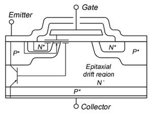
The IGBT, in contrast to the MOSFET, is a minority-carrier device. When switched on, the high concentration of carriers in the drift region keeps resistance low and any forward drop relies predominantly on the drift region’s thickness, not on the inherent resistivity. Today's IGBTs also use the vertical topology to improve their power handling capability.

Figure 2: Cross-section of a basic IGBT structure.
There is a downside to the IGBT: it cannot switch as quickly as an equivalent power MOSFET. The cause is stored charge in the bipolar transistor that must be cleared when the device is switched off. This tail time can be reduced, but at the cost of increased voltage drop. Work is ongoing to decrease the tail time without incurring a large voltage drop, so that IGBTs can move into applications with switching frequencies above 10 kHz.
A further issue is that conduction is only in one direction, although this issue has an often-used workaround in the form of a diode arranged in parallel that conducts in the reverse direction. This is useful in motor-control applications as it allows for reverse inductive current flow.
As the IGBT has bipolar transistor architecture at its core, thermal runaway is a potential issue. By changing the way in which they are fabricated, vendors have been able to overcome the issue. Traditionally, IGBTs had an n+-doped buffer layer designed to block electric fields from the collector that would otherwise “punch through” to the drift layer. Non-punch-through devices have this layer, but they stop the electric field from reaching as far as the drift layer by diffusing dopants far into the bulk silicon.
Two downsides of the NPT architecture are a lower peak voltage, because of the need to control the electric field, and lower switching time overall. Vendors have responded by making thinner devices and reducing the doping level of the n-doped collector region to cut the number of carriers that can be stored in the device and thus need to be cleared when switched off.
The result is that, for many medium- or high-power applications, such as those in motor control, the designer can potentially use power MOSFETs or IGBTs. Each offers different tradeoffs, such as switching speed versus voltage drop, but vendors are continuing to improve their designs. That can tip the balance of one or the other for different applications, particularly where breakdown voltages need not reach 1 kV.
Many motor−control applications use variable voltage, phase and frequency inverters, providing an AC output waveform from a DC supply, very often a full-wave rectified line voltage. The designs therefore often need high-voltage support – 600 V for 230 V AC inputs and 1200 V for 575 V AC. Pulse-width modulation is generally employed to provide the necessary degree of control over the AC waveform. It is often helpful to modulate at a frequency close or above 20 kHz to push audible noise out of the range of human hearing.
Another reason for increasing switching speed is to support more advanced forms of motor control that provide greater degrees of energy efficiency and accuracy. Sensorless field-oriented control methods can use high-resolution switching to provide higher sampling rates and a better reconstruction of the electromagnetic state of the motor to calculate its actual position. This combination of factors drives a requirement for MOSFETs or IGBTs to block high voltage, and can offer fast switching with low conduction losses. Devices used in motor drive applications must be robust and capable of withstanding faults long enough for protection to be activated. Devices rated for short-circuit conditions offer safe, reliable motor drive operation.
Typically, MOSFETs will be favored where higher switching frequencies are required. However, the tradeoffs between types of device can be subtle, even involving factors such as temperature. For example, the switching losses from a MOSFET can increase dramatically with temperature. If a motor design calls for operation close to peak torque for a significant proportion of its time, an IGBT may prove to be a better choice as its conduction losses are less sensitive to high temperatures. However, if the motor design operates with substantially lower torque levels than peak, the lower switching losses of a MOSFET can swing the pendulum away from the IGBT. In an industry where energy efficiency is becoming increasingly important, these considerations are key.
Vishay’s IRFP460A is an example of a power MOSFET designed to provide comparatively low conduction losses for this class of device and go into motor drives and other switched-power applications with high-frequency PWM that can reach into the 100 kHz range. The device is rated to 500 V with an on-resistance of 0.27 Ω at a gate-source voltage of 10 V.
The RC-Drives family of devices from Infineon Technologies provides support for hard-switching power conversion designs that operate at frequencies up to 30 kHz, moving the IGBT into a range previously occupied solely by power MOSFETs. An example is the IKD03N60RF, which contains a number of features to support drives and similar designs.
Whereas some IGBTs incorporate a reverse recovery diode in the package, the RC-Drives architecture pulls the ability to support reverse current flow into the core transistor itself. The device architecture is built around an asymmetric structure with a field-stop layer, trench-style gate and an emitter implanted in the backside of the wafer together with a cathode. Reverse-current flow is conducted via the cathode. There are two families of RC-Drives device. The high-speed RC-DF family, of which the IKD03N60RF is a member, uses a different doping profile to increase its switching speed, but keeps the same physical structure.
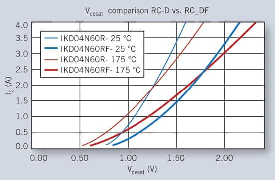
Because it is optimized for faster switching, the conduction loss from an RC-Drives F series device is higher than the lower speed RC-D products. However, the switching loss is at least 50 percent lower compared to the lower frequency devices. The RC-D family tends to show lower conduction losses over the temperature range to 175°C, with losses in the RC-DF increasing slightly with higher temperature compared to the RC-D family. The IKD03N60RF itself is a 600 V device with a current-carrying capability of 2.5 A, and a saturation voltage drop of 2.2 V at 25°C.

Figure 3: Comparison of the saturation voltage versus current for equivalent transistors in Infineon’s RC-D and RD-DF families of IGBTs.
Based on the company’s advanced punch-through technology, the STMicroelectronics STGD3HF60HD is designed to be a fast-switching IGBT and includes a high-speed, soft-recovery reverse diode integrated into the package. The 4.5 A, 600 V device has a turn-off delay time of just 60 ns to support the use of high-frequency PWM techniques. To reduce EMI issues, the STGD3HF60HD supports a low peak current during the turn-on phase with a smooth collector current shape during turn-off. STMicroelectronics has coupled the device with the L6391 controller and gate driver in an evaluation board and reference design.
The International Rectifier IRGB4060 is based on a low saturation voltage trench IGBT technology and also offers comparatively low switching losses. The 1.55 A, 600 V device is packaged with a soft-recovery reverse diode and offers a turn-off delay time of 95 ns to 106 ns to support comparatively high switching frequencies.
By working on doping profiles and device architectures, transistor suppliers have developed power MOSFETs and IGBTs that provide excellent support for advanced motor-control algorithms. The varied properties of MOSFETs and IGBTs make it possible for designers often to consider both and select the device with the correct profile for their application.

免责声明:各个作者和/或论坛参与者在本网站发表的观点、看法和意见不代表 DigiKey 的观点、看法和意见,也不代表 DigiKey 官方政策。


 中国
中国