New Stepper Motor ICs Simplify Security Camera Positioning Design
投稿人:DigiKey 北美编辑
2016-08-18
Safety and security concerns worldwide have driven a large increase in the usage of security and surveillance cameras, often with high-resolution CCD or CMOS imagers that are tied into cloud-based video analytics for biometric and facial recognition analysis.
However, for biometric algorithms to work properly, camera-positioning systems must have smooth operation to avoid unwanted image distortion while the camera is in motion. Many applications where discretion or remote access are requirements also demand that the system be compact and energy efficient.
Linear servomotor positioning systems can provide the smooth operation required but they come at the expense of higher power and the need for high-resolution encoders and precision circuitry. Alternatively, stepper motors have several attractive features for video surveillance positioning, including full torque at standstill, excellent start, stop, and reverse response times, repeatability of movement without error accumulation, and simple open-loop control with a fixed step size.
However, the fixed step size is a limitation – even a 200 step/rotation motor will have a step size of 1.8° which is not smooth enough for high-resolution video. This can be overcome with microstepping, and new microstepping driver ICs are enabling designers to quickly realize compact high-resolution, low-power positioning systems.
Stepper motor basics
A stepper motor is a brushless DC motor that divides a full rotation into an equal number of steps. The stator contains a fixed number of wound electromagnets. There are three types of rotor construction – permanent magnet (PM), variable reluctance (VR) and hybrid. PM motors have alternating north-south permanent magnets embedded around the circumference of the rotor. VR rotors are made of a soft magnetic material and have teeth cut into them (viewed on end, the rotor looks rather like a gear). VR motors operate on the principle that minimum reluctance occurs with minimum gap, thus the rotor teeth are attracted toward the stator magnet poles.
The hybrid stepper has a toothed rotor like the VR motor, as well as an axially magnetized concentric magnet around its shaft. This arrangement provides step sizes similar to the VR motor (the possible number of teeth is larger than the possible number of magnets in the PM rotor) with improved torque characteristics.
The number of phase windings in the stator is usually two, although three- and five-phase motors are also available. The motors can be wound in two ways – unipolar or bipolar. Figures 1 and 2 show the two options in a two-phase motor.

Figure 1: In a two-phase unipolar winding, the center tap is tied to the motor voltage and the phase legs switched to ground to change the direction of the current flow. (Diagram drawn using DigiKey Scheme-It)
The unipolar winding has one winding per phase with a center tap. The center tap is usually tied to the motor voltage supply, and the two ends of each winding are alternately grounded to reverse the direction of the field provided by that winding. This makes the motor simple to control, but the motor efficiency is lower as only one-half of the windings are used at a time.

Figure 2: In a two-phase bipolar winding the phase currents are reversed using an H-bridge driver, allowing the total winding to be energized at once. (Diagram drawn using DigiKey Scheme-It)
The bipolar arrangement uses all of the phase winding, but switching the drive current is more complicated. Typically, this is done with an H-bridge driver, which can also control the current in the winding (motor torque is proportional to the current.)
Stepper motors used in surveillance cameras are typically the two-phase hybrid or PM bipolar variety. In a two-phase motor the electromagnet pairs in the stator are offset slightly so that as one winding is de-energized and the next one is turned on, the teeth will be attracted to the next position. This allows for the number of steps to be four times the number of rotor teeth. Thus, a 50-tooth rotor has 200 steps per rotation, or 1.8° per step.
Step sequencing
Bipolar stepper motors have two windings. The rotor is moved by varying the current in the windings sequentially. A convenient way to visualize this is with a phase diagram.
Figure 3 shows full-step operation using the bipolar winding found in Figure 2.

Figure 3: In a full-step operation, the phase current in each winding is either -Imax or +Imax. Each state change moves the motor one step. (Source: DigiKey)
In full-step operation the current in each winding is either -Imax or +Imax. The change in phase currents shown in the Figure 3 timing diagram will result in the Figure 3 phase diagram position sequence. Each 90˚ state change around the phase diagram moves the motor one step. The length of the phase diagram arrow (phasor) is shown in EQ1:
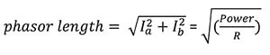
Torque is directly proportional to current (until magnetic saturation) and the phasor length gives an indication of the power draw. Of course this is the ideal case and neglects the instantaneous effects of the winding characteristics.
Figure 4 shows half-stepping operation. Here current in each winding is allowed to be -Imax, 0, or +Imax. This allows for “half steps” in between the full steps, and so doubles the number of steps per revolution, allowing for finer positioning. However, there is a price to be paid. Note that the phasor length is shorter (about 70%) on the axis when one winding value is 0. This torque ripple can be somewhat mitigated by increasing the current in the other winding.

Figure 4: In half-step operation, the current in each winding is -Imax, 0, or +Imax. This doubles the number of steps but there is current and torque ripple. (Source: DigiKey)
If you carry the concept of half stepping a little further, and allow the current in the windings to vary in a way that simulates a sinusoidal AC waveform with a constant phasor length, as shown in Figure 5, you can achieve much finer resolution with low torque ripple. This is generally referred to as sine-cosine microstepping. In Figure 5 the number of micro steps within a full step is four. This is known as divide-by-four microstepping.

Figure 5: In divide-by-four sine-cosine microstepping, torque ripple is reduced by varying the phase currents in a simulated sinusoidal AC waveform. (Source: DigiKey)
While there are drivers that can support up to divide-by-256 microstepping, in practice, the minimum step size and the step repeatability are a function of the load dynamics, the motor winding characteristics, and the driver voltage and current capability.
Integrated drivers to the rescue
Surveillance camera positioning systems often require pan rates from a few degrees to over 200˚/second and tilts rates of 5˚to 10˚ per second. The mechanism torque range is generally around 10 oz-inch and the motor input voltage typically ranges from 12 V to 40 V.
Microstepping provides the smooth step capability, fast pan, tilt and zoom rates, and accurate positioning needed for surveillance camera systems. However, the drive electronics to meet these requirements are complex. Fortunately, there are good integrated driver products on the market that greatly simplify the job.
The A5984 from Allegro Microsystems is a microstepping driver with translator well suited to single-axis camera-positioning applications. It can provide full-, half-, and microstepping modes up to divide by 32. It has an operating voltage range of 8- to 40-VDC and can source and sink up to 2 A per phase. It comes in 24-pin QFN or TSSOP packages to fit easily in small-form-factor positioning systems. The packages both feature exposed pads to help with thermal management.
Figure 6 shows the functional block diagram of the A5984. The DIR pin determines the motor direction and the STEP pin advances the motor either full or fractional steps, depending on the MSx pins. The MSx pins select full-step, half-step or divide-by-4, 8, 16, or 32 microstepping modes. The translator takes care of the phase sequencing required to implement these modes. The control software only needs to set the direction and pulse the STEP pin for every increment of movement. This allows the use of a simple, low-cost, low-power MCU.

Figure 6: In Allegro Microsystems’ A5984 microstepping driver with translator, internal dual H-bridge drivers are controlled by a translator, internal control logic, and a constant off-time pulse-width-modulation (PWM) driver for ease of use. (Source: Allegro Microsystems)
The currents in each phase are regulated via a fixed off-time pulse-width-modulated (PWM) control. A special feature is the adaptive percent fast decay (APFD) current-control mode. The APFD automatically adjusts the amount of decay in the current-control chopper circuit on a step-by-step basis. This eliminates the problem of current continuity through zero, which can result in missed steps at slow speeds (Figures 7 and 8). This feature is important in camera positioning systems as missed pulses appear as motion jerk. APFD also reduces current ripple overall in the system, enhancing smooth operation.

Figure 7: Fixed chopper decay times can result in missed pulses at the zero cross at slow stepping speeds. (Source: Allegro Microsystems)
")
Figure 8: Adaptive Percent Fast Decay (APFD) adds an appropriate amount of fast decay per pulse to eliminate current discontinuities and missed pulses at slow speeds. (Source: Allegro Microsystems)
The motor outputs are automatically protected from shorted load and shorts to battery or ground by disabling the outputs. These faults are reported via the nFAULT pin. Undervoltage lockout and thermal shutdown are also provided for additional protection.
Other devices in this driver family are available including dual drivers for two axis applications.
Ultra-smooth dual driver
Another approach to position system motion control can be found in the LV8714TA from ON Semiconductor. This is a dual-stepper motor driver so it can handle both pan and tilt duties. It can drive motors from 8 to 16 V at up to 1.5 A per phase. It comes in a space-saving 7 x 7 mm TQFP exposed pad package (Figure 9.)

Figure 9: The LV8714TA from ON Semiconductor integrates dual stepper motor drives so one part can drive both pan and tilt motors. (Source: ON Semiconductor)
Each motor is controlled by two enable pins and two input pins. The phase input sequence on the input pins determines the direction of the step as shown in Table 1.
| INx | ENA1, ENA2 | Phase | Direction | |||
| 0-90 | 90-180 | 180-270 | 270-360 | |||
| IN1 | H | L | L | H | H | Forward |
| IN2 | H | H | L | L | H | |
| IN1 | H | H | L | L | H | Reverse |
| IN2 | H | L | L | H | H | |
Table 1: LV8714TA stepper direction is controlled by the phase input sequence on the motor INx pins. (Source: ON Semiconductor)
Unlike most stepper motor drivers, the LV8714TA does not employ external current-sense resistors. Instead it uses a proprietary internal current-sense mechanism to monitor and control the coil current in combination with VREFx pins (one per motor phase). The max desired coil current in a phase is set by a resistor tied to the RCSx pin. A constant value on that phase VREFx pin will produce a constant current to that phase, and a full step will be taken at every phase transition, per Table 1.
However, if 90˚ offset, fully rectified voltage sine waves – synchronized to the phase inputs – are applied to the VREFx pins of a motor phase pair, the coil current will vary through the step sequence, creating microstepping. In this way, greater than divide-by-256 microstepping can be achieved, resulting in ultra-smooth operation (Figure 10).

Figure 10: On the LV8714TA stepper driver from ON Semiconductor, the INx pins and full wave rectified sine voltage waveforms on the VREF pins combine to create fine microstep coil currents. (Source: ON Semiconductor)
The tradeoff for this performance is more software complexity, as the host microcontroller needs to control both the INx pins and the VREFx pins throughout the step sequence. The VREFx waveforms can be controlled via an appropriate digital potentiometer or a digital-to-analog converter (DAC).
The device offers under-voltage, over-current and over-temperature protection features and has a very low standby current of 1 µA (typical).
Conclusion
Surveillance-camera positioning systems need smooth and accurate operation to meet the needs of high-resolution cameras and advanced surveillance software. Bipolar stepper motors combined with the right microstepping controller can provide this level of performance while meeting cost, energy efficiency, and packaging needs.
免责声明:各个作者和/或论坛参与者在本网站发表的观点、看法和意见不代表 DigiKey 的观点、看法和意见,也不代表 DigiKey 官方政策。