Managing Power Distribution via Power over Ethernet (PoE) in Hardwired Networks
投稿人:DigiKey 欧洲编辑
2013-08-13
Hardwired Ethernet networks are ubiquitous in most offices to the point where non-infrastructure experts may take this infrastructure for granted. However, in delivering reliable systems, focus continues on the part of both OEMs and chip suppliers towards further improvements. Improvements in operability, service and implementation cost are driving increased functional integration and the development of more specialized silicon solutions.
Ethernet has been around for many years, however, perhaps surprisingly, this year celebrates the first decade of the existence of the Power over Ethernet (PoE) market. This quiet revolution allowed IP products to avoid being tethered to a power source. Hard to believe that, in that time, we have seen IP phones replace our old ISDN telephone networks.
This article considers current technical trends, challenges, and solutions used to update the capabilities of PoE with the drive towards delivering increased power remotely via Ethernet infrastructure. In doing so, it will consider a couple of the latest PoE solutions. Of course, the provision of PoE affects both ends of the Ethernet cable. In this first article, we will consider the remote power sink (the power device or PD).
The parts discussed here include both fully integrated PD solutions such as Maxim’s MAX5986, Texas Instruments' TPS23785, and ON Semiconductor’s NCP1081. These combine the PoE signaling function with a local DC/DC converter for single chip PD implementation. We will also look at several PD interface controllers that handle just the PoE network signaling protocol, useful for designers that already have a high voltage DC/DC design but need to be able to comply with the PoE signaling needs. Two parts are discussed here are TI’s TPS2379 and Linear Technology’s LT4275.
Development of PoE standards
It is around a decade ago (June 2003), following initial work by Cisco, that the IEEE ratified the IEEE802.3af specification that opened the market to the possibility of remotely powered devices (PDs, as they are referred to in standards terminology). At this point, the intention was to provide limited power over the existing CAT-5 cable infrastructure to power devices like VoIP phones where the originally specified power source of 13 W was more than adequate for that task. Six years later in 2009, the new IEEE802.3at standard arrived. This, often denoted as PoE+, expanded the sourced power capability through existing cable infrastructure to 25.5 W. In both cases, a single differential pair of CAT-5 cable is used for power delivery. Both variants of the standard account for DC power losses in lengths of cable by defining both a nominal maximum current draw and anticipated cable losses, and thus, power delivered to the PD.
This market continues to grow and according to Global Industry Analysts, in their report of August 2012, the global PoE chipsets market is set to grow to > $200M by 2018, making this a significant power market in its own right.
No sooner had basic PoE applications started to emerge, than it became obvious that networks could easily exploit more remote power. Creative engineers started to look at pushing the power envelope in support of increased functional needs from markets - powering industrial networking systems, building monitoring systems, monitors, thin clients, security cameras, and so on. In the latest round of developments, technologists have looked to achieve 60 W to 90 W of remote power. This is especially exemplified by developments at Linear Technology. The company now promotes a backward compatible (but proprietary) PoE classification called LTPoE++. The full range of PD power capabilities of this system is listed in Figure 1 below (courtesy of LTC).
| Standard | PoE Type | PD input Power | Useable Power |
| PoE (IEEE 802.3af) | Type 1 | 13 W | 11.25 W |
| PoE (IEEE 802.3at) | Type 2 | 25 W | 22 W |
| Linear Technology LTPoE++ | LTPoE++ | 38.7 W | 32.9 W |
| LTPoE++ | 52.7 W | 44.5 W | |
| LTPoE++ | 70 W | 60.8 W | |
| LTPoE++ | 90 W | 76.8 W |
Figure 1: Range of PD powers supported by IEEE 802.3x and new LTC LTPoE++ classification.
Functional needs of the power delivery (PD device)
Power delivery via PoE is enabled by two separate delivery methods. The most straightforward is defined in the standards as Alternative B. This simply exploits unused conductor pairs in a standard Ethernet cable to transfer power. This is possible since only two of the four pairs are needed in support of common 10 Mbit/s and 100 Mbit/s systems.
A second, more advanced powering scheme exists, even if all conductor pairs are needed in highest speed implementations, and that is known as Alternative A. This option transmits power on the data carrying conductors through the application of a common mode voltage to each conductor pair. Common with many high-speed cable based signaling systems, Ethernet uses a differential signaling approach to provide robust, low error-rate communications. The applied common mode signal can co-exist with the data signal, as the data receiver is only interested in 'seeing' differential signal swings and not the overlaid common mode power signal. The power is easily extracted at the remote end via the signal Rx transformer.
Wrapped up within the IEEE802.3x PoE specifications are a set of protocols to manage the network and handle operating methodologies. Many advantages are touted for PoE implementations, not least the simplicity of wiring data throughout large organizations. Adding power to the mix means rapid system implementation and deployment. Furthermore, in the context of efficient switching power supplies, these protocols allow for power saving throughout the entire network and certainly offer superior power performance when compared to using many unmanaged and often underused energy vampires (wall power adapters).
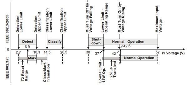
The specification requires the PD to be able to support both powering alternatives (A & B) and to be able to signal its power capabilities back to the PSE. The power-up sequence for a PoE link is designed to provide this information and comprises three steps: initial detection, classification, and start-up. Detection requires a nominal 25k resistor to be applied between powered pairs at the PD, and this allows the remote sourcing end to determine the state of the power lines to the PD. To determine this, the PSE applies a classification voltage across the power conductor pairs and measures the resulting current through the PD. This confirms to the PSE the maximum power handling capability of the remote PD. Once the correct control signaling has been completed, the system moves into start-up or normal powered operation. For fault free operation of the PoE link, the PD is required to present the maintain power signature (MPS) continuously. Loss of MPS signature results in a powered link being shut down by the PSE. A good description of the various PD operating states (and signaling) can be found in the TPS23785B data sheet reproduced in Figure 2 below.

A significant aspect for PoE is the ability to drive power over relatively long cable lengths, perhaps up to 300 feet (100 m). As with all DC systems, the line loss will be decided primarily through the conductive resistive losses of the line. In the case of CAT-5 cable, the safe power handling limits are considered to be around 360 mA at 50 V. Given two spare data pairs, that allows 36 W (50 x 0.36 x 2) in the cable. However, over a 100 m run, around 4.5 W of that 36 W is lost in conductive heating leaving just shy of 32 W available at the sink. Additional improvements are available if better grade CAT-6 cabling is available.
A selection of the latest PoE power device solutions
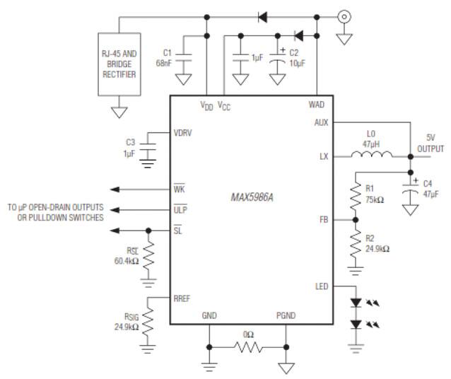
Claiming a significant reduction in bill of material needs, the MAX5986A/B provides a complete solution for PoE (IEEE802.3af) powered devices. The MAX5986A/B integrates a PoE interface system combined with a peak current controlled step-down DC/DC converter operating at a few hundred kilohertz. It offers a fixed 3.3 V or adjustable output up from 3.0 to 5.6 V (MAX5986A) or up to 14 V (MAX5986B) with a simple resistor divider along with an output voltage monitor function. The parts provide fast transient response, and are guaranteed to operate from an input voltage level between 8.7 and 60 V. The A grade part delivers 201 mA and the B grade supports 323 mA. The device limits start-up in-rush current to 60 mA/49 mA (max/typical).

A great feature of the device is its integrated transient suppression circuit, for which it is claimed the PD can survive a defined transient event with a voltage up to 100 V applied through a 3.3 kΩ test resistor for 100 ms. This helps ensure survivability in the face of hot plugging cable related transients, and Maxim indicates it can pass a 2 kV, 200 m CAT-6 Cable discharge event (CDE).
Given legacy products still in use in the market, the MAX5986 offers simplified handling of traditional local power such as that available from a wall adapter using the wall adapter detection function (WAD, pin 12). This pin detects the presence of a wall adapter when the voltage on this pin exceeds 8.8 V. At this point, the internal isolation power MOSFET is turned off and the device turns off the classification current function, essentially ensuring the PSE disables power on the specific lines to the remote PD.
Other features of Maxim's PD part include the provision of an LED driver circuit, capable of driving 10-20 mA and sleep and ultra-low power modes. In the case of sleep mode, current consumption is reduced to around 62.5 μA. The datasheet claims the MAX5986 'allows the devices to reduce power consumption lower than sleep mode, while maintaining the power signature of the IEEE standard', but does not provide an absolute guarantee for this current level.
In contrast to the relative simplicity of the Maxim PD solution, the second device from TI, the TPS23785B, offers a wider diversity of functional options at the expense of slightly more complexity. It supports input power up to 30 W, a little beyond the capabilities needed to fully meet Type 2 applications (See Table 1 above). In common with the Maxim solution, this part combines the PoE interface functions with an on-chip, non-isolated fly-back mode DC/DC converter.
Two complementary gate drivers are provided by the TPS23785, each with programmable dead time, which simplifies the design of efficient fly-back topologies. The second gate driver can be disabled if a simpler, single MOSFET design is desired. This controller comes complete with internal soft-start, current mode compensation and supports a maximum duty cycle of 78%. Oscillator programming is limited with the data sheet claiming a range from 227 to 278 kHz.
One noteworthy aspect of this part is that it will support so-called adapter OR-ing. Similar to the WAD function mentioned for the Maxim part, the TI approach provides a little more flexibility as the part can be forced to operate based on highest input voltage, external adapter preference or PoE preference. This gives designers a useful tool to pre-determine the behavior of the PD device without needing extra external circuitry to implement this function.
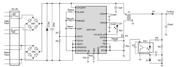
A third integrated PD controller and DC/DC converter is available from ON Semiconductor. The NCP1081 supports extended PD power up to 40 W. The DC/DC controller block of the NCP1081 offers configurations supporting isolated and non-isolated fly-back and forward as well as step-down conversion topologies. Current mode control is implemented here and it can be programmed to deliver up to 1100 mA continuously. The datasheet for the NCP1081 does a good job to highlight typical power supply topologies for each supported configuration and numerous design tips are provided for the part.

The DC/DC loop works over a broad range of duty cycles and a user programmable switching frequency range from 100 kHz to 500 kHz, set by a single external timing resistor, aids component selection flexibility. In addition, the soft-start feature is programmable via a single external capacitor. Finally, individual resistors are selected to program in-rush and operating current limits for the NCP1081. Further protection afforded by this part includes thermal shut down and adjustable under-voltage lockout.
To avoid sub-harmonic oscillations and potential instability from continuous conduction mode operation, the device implements a slope compensation scheme. The versatile NCP1081 is packaged in a thermally enhanced, 20-pin TSSOP.
For any one of the DC/DC converters mentioned here, there will be the need to source suitable passive components. The inductors are probably the most important elements and DigiKey supplies PoE transformers from both Eaton's Coiltronics brand and Wurth Electronics. It is worth looking at the Coiltronics PoE application note (#4036).
PoE Interface Controllers
An alternative to a PoE interface and power supply combo chip, and available especially for designers who already have a potential PD power supply solution in-house, is a special PoE interface controller function offered by several vendors. Texas Instruments has a simple solution in its TPS2379. This part delivers a protected interface in a tiny, 8-pin, power SO-8 package. The controller can handle continuous current of 0.85 A. It supports high power applications using an external pass transistor to help with thermal management. Robustness comes from 100 V capable internal structures. The device limits in-rush currents to 140 mA and provides Type 2 (IEEE802.3at) classification and auto-retry fault protection. The output from the TPS2379 is an enable signal (CDB, pin 6), which is used to switch on the primary power device's DC/DC supply.
Linear Technology (LTC) has some of the most innovative mixed-signal devices and the LTC4275 PD controller is an example. LTC has enhanced its Ethernet credentials by developing a propriety PoE classification they call LTPoE++. The new classification is both backward compatible with existing standards (IEEE802.3af and .3at) and delivers up to 90 W input power for powered devices. It is supported at both ends of the cable with LTC solutions. In the case of the PD interface IC, the LT4275, it takes integration a step further by including the signature resistor (LT4275A only), eliminating external protection elements and delivering the part in a tiny 10-pin device (either DFN or MSOP packages). Resorting to external pass devices helps with thermal design, since the pass device can be selected according to the needs of individual target specifications of the PD whilst minimizing power dissipation.
In this review, we have covered several of the current crop of solutions available to the designer to implement powered devices. This is by no means exhaustive and several extra 25 W and higher PD solutions are launching to production this year from other vendors not mentioned here. There is, however, a reasonable choice available today for the PD function and it is clear that delivered power can start to reach beyond 50 W, enabling PoE to target more power hungry applications in the future.
Reference:
- Global Industry Analysts report (MCP 6766) on PoE chipsets, as reported in their August 2012 press release

免责声明:各个作者和/或论坛参与者在本网站发表的观点、看法和意见不代表 DigiKey 的观点、看法和意见,也不代表 DigiKey 官方政策。


