Innovations in Connectivity: The DigiKey Weather Center Smart Charger
投稿人:DigiKey
2011-08-08
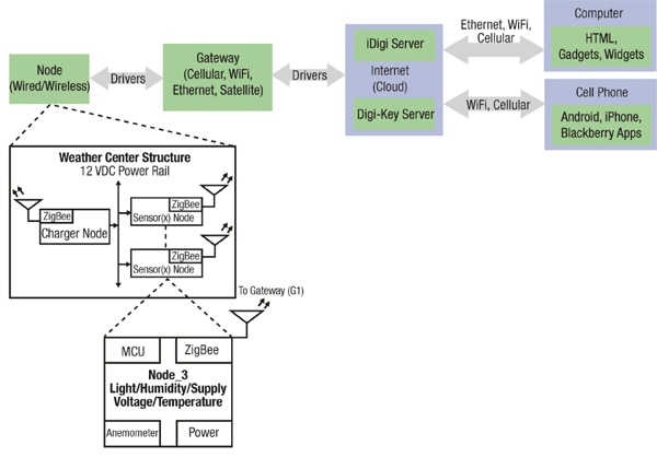
The DigiKey Weather Center utilizes the best in electronic components to test conditions in an environment where conditions vary greatly. The diagram below depicts the process in which DigiKey's Weather Center conveys the data collected to computers and mobile devices.
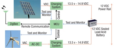
Designed to utilize alternative energy sources such as a solar panel or a wind turbine to charge a sealed lead acid battery, the Smart Charger is based around an Atmel MEGA1281 AVR. It is at the heart of the DigiKey Weather Center's design to monitor and control the charging circuits for the energy inputs. Figure 1a shows a block diagram of the Smart Charger system and its functionality. Figure 1b is an image of the Smart Charger prior to its installation in the Weather Center.

Smart Charger circuits
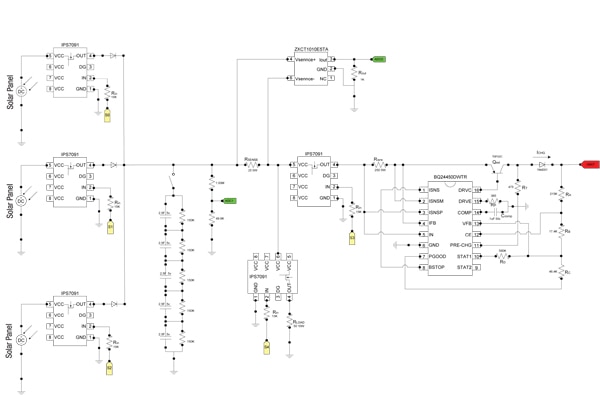
The two alternative energy sources are connected to two separate, though similarly designed charging circuits. The charging circuits are based on the Texas Instruments' BQ24450, a linear-designed regulator which monitors the battery voltage with a voltage divider circuit. In conjunction with the charging IC, some additions to the solar charging circuit (Figure 2) have been made, including the Zetex ZXCT1010 to measure the current through a sense resistor, and a series of resistors arranged in a voltage divider configuration. These two modifications allow the controller to measure the input voltage and current from the solar panels. Secondly, five IPS6031 high side switches from International Rectifier were added to allow the controller to connect or disconnect various inputs in and out of the circuit for a couple of different reasons. The first reason is to control the solar inputs individually in order to get maximum solar power, and the second reason is to allow testing of each solar panel individually for maximum life and performance. Lastly, five Ultra capacitors from NESSCAP were added to the input of the circuit to allow intermittent solar inputs to have a minimal effect on the charging of the battery.
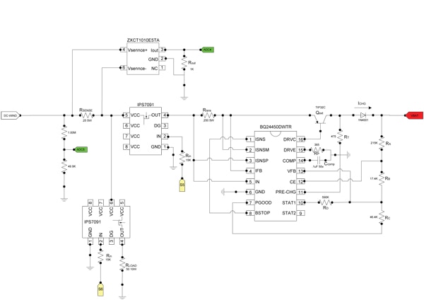
The wind turbine charging circuit (Figure 3) is designed around the same BQ24450 with the same voltage and current monitoring additions along with two switches to control an input load, but with only one DC input from a 3-phase wind turbine which has already been rectified into DC.
Battery monitoring
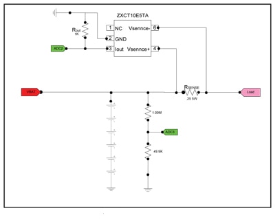
Monitoring of the Smart Charger battery (Figure 4) is accomplished with a simple voltage divider to monitor the voltage across the battery, and a current sensor ZXCT1010E5TA from Zetex to monitor the charge and discharge current of the battery.
Smart Charger control
The microcontroller used in this design is the AVR ATMEGA1281 from Atmel. This microcontroller was selected for various reasons, including personal familiarity with programming and debugging tools which allowed for rapid development and testing of the program and circuit. The numerous analog and digital I/Os (Figure 5) on the device are integral in the monitoring and control of the entire board. The multiple digital I/Os allow the controller to have full control over the high-side switches used to control various parts of the circuit board, and the analog I/Os allow the controller to monitor the voltage and current of both the inputs and outputs. Along with monitor and control capabilities, the controller has multiple communication ports which allow other devices to be connected. In particular, the circuit board is using the UART to communicate through an XBEE module to a remote Ethernet gateway, giving remote access to the board. The controller has 128 KB of Flash memory for program code, which is more than enough for this implementation and allows for future program updates or additions.
ZigBee communication
The XBEE module (Figure 6) from Digi International provides a wireless connection to the Smart Charger, utilizing the ZigBee protocol over the 2.4 GHz frequency band. By using the XBEE with the ZigBee protocol, the Smart Charger functions like another node on the network. Using the module in a data pass-through mode the controller does not have to deal with the ZigBee protocol. This allows the controller to pass data as it would through a wired RS232 communication network. Finally, the ZigBee network is equipped with a ZigBee enabled Ethernet gateway device. This device is able to communicate over the Internet via the Ethernet port and relay any information through the ZigBee network, making the Smart Charger accessible over the Internet for control and monitoring.
Load control
Each load attached to the charger can be controlled individually by the MCU using an IPS6031 high side driver (Figure 7) as a switch. This gives the MCU flexibility to monitor each load independently in order to determine the impact each one has on the system or monitor the entire load.
After installing the Smart Charger on the DigiKey Weather Center (Figure 8), the solar voltage, current input, current output, and load voltage are measured and collected by the AVR, and then sent to a data base via the XBEE module and ZigBee network. The most recent data can be viewed on connectivity.digikey.com. For schematics, source code, and diagrams please visit www.eewiki.net/display/WeatherCenter.


免责声明:各个作者和/或论坛参与者在本网站发表的观点、看法和意见不代表 DigiKey 的观点、看法和意见,也不代表 DigiKey 官方政策。


