How to Implement Galvanic Isolation for Power and Signal Lines in High-Voltage Systems
投稿人:DigiKey 北美编辑
2023-01-27
Robust protection for devices and users is required in the presence of power and signal lines across a range of high-voltage applications, including Industry 4.0 systems like factory automation and motor drives. This extends to automotive and electric vehicles (EVs), medical systems, test and measurement applications, and green energy systems such as photovoltaic systems and grid infrastructure. To achieve this protection, some form of isolation is required.
The challenge for designers is to ensure the isolation mechanism is compact, efficient, and cost effective, while also supporting bidirectional signal transmission and power transfer. Because the isolation mechanism must provide operator safety from high voltages and ensure reliable system operation, isolation devices must meet standards like International Electrotechnical Commission (IEC) 60747-5 and IEC 60747-17.
Traditional approaches to galvanic isolation using optocouplers or transformers can satisfy the IEC standards but have limitations in some applications. To more reliably meet device and user protection requirements, while also providing bidirectional signal transmission, galvanic isolation using capacitive and magnetic technologies is required.
This article briefly introduces galvanic isolation. It then reviews the IEC standards and looks at how galvanic isolation can be implemented using integrated capacitive and magnetic technologies. It presents example galvanic isolation solutions from Texas Instruments for applications including general purpose isolators that combine capacitive and magnetic technologies. Evaluation boards that speed the design process are also discussed.
The role of galvanic isolation
Galvanic isolation prevents current flow between functional sections of electronic or electrical systems, but supports the transmission of analog and digital signals and power between the sections (Figure 1). Galvanic isolation is useful for:
- Connecting functional sections that have different ground potentials
- Breaking ground loops by stopping current flow between functional sections sharing a ground
- Protecting operators from shock hazards from high-voltage sections
 Figure 1: Galvanic isolation allows data and/or power flow, but no ground currents between isolated sections. (Image source: Texas Instruments)
Isolation types and choices
There are several isolation types to choose from and different international standards governing their use, like IEC 60747-17 for magnetic and capacitive isolation and IEC 60747-5-5 for optocouplers (Table 1).
- Functional or operational isolation ensures proper system operation but does not protect users from high voltages. It’s not covered by safety regulations.
- Basic isolation is the simplest form of isolation that’s included in safety regulations. It can protect users from electrical shock, but if it fails, users could still be exposed to a high voltage.
- Supplementary isolation adds a layer on top of basic isolation. It protects users from high voltages if the basic isolation fails.
- Double isolation is not a separate type of isolation. It refers to using both basic and supplementary isolation. However, most standards and safety documents refer to double isolation as a type of isolation.
- Reinforced isolation is a single isolation system that provides protection equal to double isolation. The performance and testing requirements for reinforced isolation are more stringent than for basic or supplementary isolation approaches.
 Table 1: Testing and operational requirements for reinforced isolation are more demanding than for basic isolation. (Table source: Texas Instruments)
While optocouplers are widely used for galvanic isolation purposes, they can only be used on signal lines, they tend to be inefficient, can send data in only one direction, and have bandwidth limitations. Optocoupler bandwidth can be improved by adding LED drive circuitry and amplifiers, but that results in higher costs and increased energy consumption. Using a transformer to provide magnetic isolation can provide an efficient solution for power and high-speed signal lines, but discrete transformers are large and costly.
To reliably and more effectively meet the demands of galvanic isolation, designers can turn to integrated capacitive and magnetic solutions that meet the IEC isolation standards. Capacitive isolators support analog signaling and high-speed bidirectional data transmission, with limited power transfer capability. Integrated magnetic isolation can support bidirectional transmission of high-speed data and the transfer of higher levels of power.
Isolation characteristics
Isolation voltage, working voltage, and common‐mode transient immunity (CMTI) are three key characteristics of isolators. Isolation voltage specifies the maximum voltage at which the isolator can protect from dangerous voltages for a short time. The working voltage is the long-term voltage at which the isolator is designed to be used.
CMTI is the maximum slew rate (frequency) of transients on the common voltage applied between two isolated circuits that can be withstood with no adverse effect on data transmission across the isolation barrier. CMTI is specified in kilovolts per microsecond (kV/μs) or volts per nanosecond (V/ns). The capacitance between the isolated ground planes is the path where transient energy can cross the barrier and corrupt the data or waveform. A high CMTI indicates a system that is robust and where the two sides operate within specifications even when exposed to fast transient events. A low CMTI can result in distortion, missing information, jitter, and other signal integrity problems. A CMTI of 100 V/ns or higher indicates a high-performance isolator.
In addition to electrical specifications, isolators must satisfy mechanical requirements related to clearance and creepage distances. Clearance is the distance between adjacent conductors through the air, while creepage is the distance between them across the surface of the package.
Various package styles and sizes provide different levels of creepage and clearance performance. The selection of the mold compound and the use of insulator materials with the needed dielectric strength are also factors that determine the isolation rating. The dielectric strengths of commonly used materials are:
- Air ≈ 1 volt root mean square per micrometer (VRMS/μm)
- Epoxies ≈ 20 VRMS/μm
- Silica-filled mold compounds ≈ 100 VRMS/μm
- Polyimide polymer ≈ 300 VRMS/μm
- Silicon dioxide (SiO2) ≈ 500 VRMS/μm
Galvanic isolation technologies
Optocouplers use an LED to transmit analog or digital signals through a dielectric insulator to a phototransistor. As mentioned, they are one-way devices. Common insulating materials used in optocouplers include air, epoxy, or mold compounds. Since these materials have relatively low dielectric strengths, a greater physical distance between the LED and phototransistor is required to achieve a given level of isolation.
Capacitive isolation uses a SiO2 insulation barrier. SiO2 has a high dielectric strength and is more stable when exposed to moisture of extreme temperatures, compared to most epoxy or mold compounds. Capacitive isolation uses various modulation techniques like on-off keying or phase-shift keying to transmit AC signals across the barrier. Capacitive isolation can be compact and can transmit high-speed signals bidirectionally but has a very limited power transmission capability, typically <100 microwatts (μW).
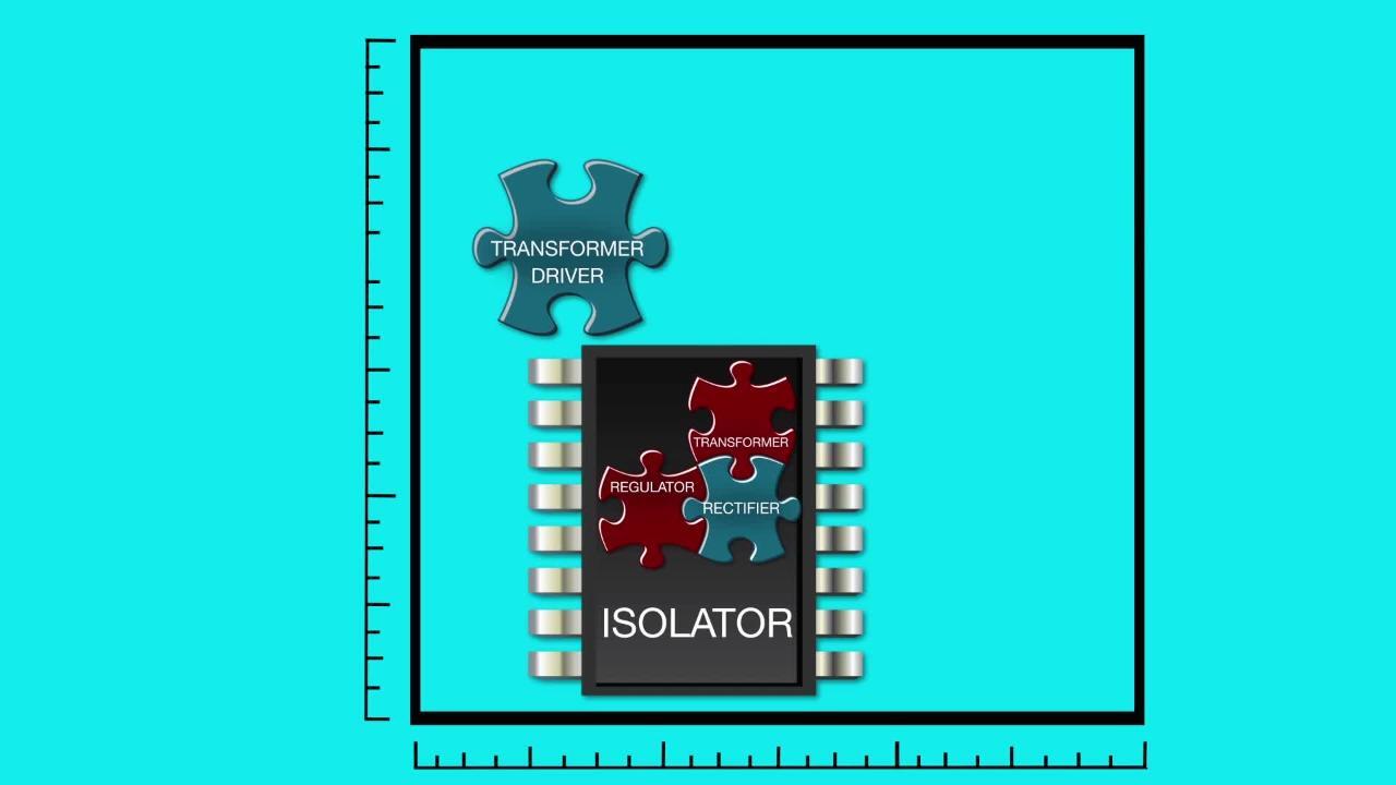
Magnetic isolators can transmit signals and power across the isolation barrier. Some of these isolators can transmit hundreds of milliwatts (mW) of power and can replace a secondary-side bias power supply. Magnetic isolators can use an air core or ferrite core. Ferrite cores can handle more power. When power needs are below about 100 mW, an air core can provide a lower-cost and simpler solution. Each of the three technologies supports different combinations of signal and power transmission (Figure 2).
 Figure 2: Optocouplers (A) can only transmit signals, capacitive isolators (B) can transmit limited amounts of power and signals, and magnetic isolators (C) can handle higher power levels as well as signals. (Image source: Texas Instruments)
Power and signal isolation
Designers that need up to 650 mW of isolated power and four isolated signal channels capable of 100 megabits per second (Mbps) transmission rates can turn to the ISOW7841FDWER from Texas Instruments. This general purpose device has an isolation rating of 5 kilovolts root mean square (kVRMS) and a ±100 kV/µs minimum CMTI. It uses SiO2 isolation on the signal channels and thin film polymer isolation for the on-chip power transformer (Figure 3). The ISOW7841EVM eval board can help designers evaluate device performance in isolated systems and speed time to market.
 Figure 3: The ISOW7841FDWER uses polymer insulation in the power transformer (top) and SiO2 isolation capacitors in the signal chain (bottom). (Image source: Texas Instruments)
Isolated automotive DC/DC
Automotive systems that need 500 mW with 5 kVRMS isolation can use the AEC-Q100 qualified UCC12051QDVERQ1 from Texas Instruments. It features a minimum CMTI of 100 V/ns, a surge capability of 10 kVpeak, and a working voltage of 1.2 kVRMS. It uses spread spectrum modulation for the internal oscillator and an optimized internal layout to minimize radiated emissions. It includes undervoltage lockout, thermal shutdown, an enable pin, a synchronization function, and delivers an output of 5.0 or 3.3 volts direct current (VDC).
The UCC12050EVM-022 eval board enables designers to test the enable/disable function, synchronize to an external clock source, detect external clock faults, and select the output voltage. It has test points for ripple and transient response measurements. The board can simplify system integration by serving as an example of a layout that supports the rated isolation and provides good electromagnetic interference (EMI) performance (Figure 4).
 Figure 4: In addition to speeding evaluation of the UCC12051QDVERQ1 isolated DC/DC converter IC, the UCC12050EVM-022 eval board provides a suggested layout for system integration. (Image source: Texas Instruments)
CAN transceivers with capacitive isolation
For applications that need a Controller Area Network (CAN) transceiver with 1 Mbps signaling and a CMTI of 50 kV/μs, Texas Instruments offers the ISO1050DWR with an isolation rating of 5 kVRMS, and the ISO1050DUB rated for 2.5 kVRMS. These transceivers meet the specifications of ISO 11898-2 for high-speed CAN operation (Figure 5). They are specified for operation from -55 to 105 degrees Celsius (°C) and include overvoltage, cross-wire, and loss of ground protection from -27 to 40 volts, overtemperature shutdown, and a -12 to +12 volt common-mode range.
 Figure 5: The isolated ISO1050DWR and ISO1050DUB transceivers meet ISO 11898-2 for high-speed CAN operation. (Image source: Texas Instruments)
The ISO1050EVM eval module with input and output connections and test points for key performance measurements can speed the integration of these devices into automotive systems.
Isolated RS-485/RS-422 transceivers
Systems that need a 500 kilobits per second (kbps) RS-485/RS-422 transceiver with 5 kVRMS isolation can select from Texas Instruments’ half-duplex ISO1410BDWR or the full-duplex ISO1412BDWR (Figure 6). The SiO2 isolation barrier supports robust data transfer in the presence of large ground potential differences. These transceivers are rated for operation from -40 to 125 °C. The bus pins are designed to withstand high levels of electrostatic discharge (ESD) and electrical fast transient (EFT) events, eliminating the need for additional protection components.
 and the half-duplex ISO1410BDWR (bottom) (click to enlarge)") Figure 6: The full-duplex ISO1412BDWR (top) and the half-duplex ISO1410BDWR (bottom) support 500 kbps data rates and feature 5 kVRMS isolation (vertical dashed line). (Image source: Texas Instruments)
Figure 6: The full-duplex ISO1412BDWR (top) and the half-duplex ISO1410BDWR (bottom) support 500 kbps data rates and feature 5 kVRMS isolation (vertical dashed line). (Image source: Texas Instruments)
Designers can use the ISO1410DWEVM and the ISO1412DWEVM eval boards to evaluate various system parameters. Test signals and sequences can be applied, and performance characteristics like propagation delay, power consumption, and different bus and driver conditions can be evaluated.
Conclusion
Designers of high-voltage Industry 4.0, automotive, medical, green energy, and other systems need galvanic isolation to protect both devices and users, while meeting size, cost, and reliability requirements, along with associated safety standards. As shown, capacitive and magnetic galvanic isolation in power and signal lines can produce compact and high-performance solutions. These isolation technologies have high CMTIs and meet the requirements of IEC 60747-17 for reinforced isolation.
Recommended Reading
免责声明:各个作者和/或论坛参与者在本网站发表的观点、看法和意见不代表 DigiKey 的观点、看法和意见,也不代表 DigiKey 官方政策。