Flyback Regulators as a First Choice for Isolated Power Supplies
投稿人:电子产品
2012-10-23
Flyback converters are rarely the first thought for the engineer looking for a suitable switching DC/DC converter ("regulator") because they can be troublesome to design in. However, if the application calls for high voltage (at relatively low power), the flyback type comes into its own.
Because it is used to generate high voltages, the flyback regulator employs a transformer to ensure galvanic isolation for safety reasons, replacing the (non-isolating) inductor used in conventional switching step-up/step-down ("buck"/"boost") regulators. The use of a transformer does, however, make this type of regulator unsuitable for high power applications.
This article takes a close look at the flyback regulator, explores its advantages and drawbacks, and describes the type of applications for which this type of regulator is best suited.
The need for isolation
A switching buck/boost voltage regulator is something of a workhorse for the power conversion engineer. Reliable, efficient, relatively easy-to-design in (although not as simple as a linear regulator —see the TechZone article "Understanding the Advantages and Disadvantages of Linear Regulators"), and in plentiful supply, buck/boost regulators such as Fairchild Semiconductor's KA34063A — a monolithic 100 Hz to 100 kHz switching power supply — often top the designer's shortlist for his/her next project.
As popular as these devices are, they do have a weakness: if the appliance that the regulator is powering requires a high voltage, there is no way of isolating that voltage from things that might find it dangerous (for example, sensitive electronic components and frail humans).
The flyback regulator overcomes this problem. By incorporating a transformer — that acts as a coupled inductor — the converter gains the galvanic isolation required to ensure safety in high voltage output applications. That makes the flyback converter useful for generating the high voltages required for equipment such as CRT tubes, insulation test equipment, photocopiers, and xenon flash lamps. (Note that while there are other isolated topologies, for example the forward converter, the flyback is the simplest and, hence, the least expensive type.)
The flyback regulator topology also brings two other key advantages: elimination of the ground loop between primary and secondary circuits, improving noise immunity (see the TechZone article "Conducted and Radiated Emissions Reduction Techniques for Power Modules"), and ease of output connections in the system without conflicting with the primary ground. Figure 1 shows how the flyback regulator's topology is derived from the buck/boost regulator design (the switching controllers have been left out of the schematics for clarity).1

Figure 1: Flyback regulator is derived from buck/boost regulator design. Note the replacement of the buck/boost regulator's inductor with a transformer in the flyback design (Courtesy of National Semiconductor).
The flyback regulator has some other subtle advantages over other types. First, the buck or boost voltage can be set initially by the ratio of turns in the primary coil to those in the secondary, then the output voltage can be subtly adjusted (as with all switching regulators) by adjusting the duty cycle of the pulse width modulation (PWM) integrated into the switching controller. Second, the flyback regulator topology makes it easy to implement multiple outputs. Third, there is no need for the output inductor required for other switching topologies and which can be a tricky device to specify (see the TechZone article "The Inductor's Role in Completing a Power Module-Based Solution").
There are some tradeoffs with the flyback design. First is the issue of high output ripple current and voltage. This can be mitigated to some extent by additional external components acting as a filter, but designing such filter circuits is challenging and time consuming. Second, and potentially the most restrictive drawback, is the flyback regulator's power limitations.
In operation, the magnetic flux in the flyback regulator's transformer core never reverses its polarity. That means it can be all too easy to magnetically saturate the core – compromising the regulator's operation — unless it is heavy and bulky for a given power output. Consequently, flyback regulators tend to be used for relatively low power applications (typically below 50 W) so that a reasonable-sized transformer can be used.
It should be noted that a high voltage on the output side is not the only reason for needing a power supply with isolation. The fact that the isolation provides a good degree of noise immunity makes the flyback design a good choice, for example, for powering communications interfaces such as RS-485 and RS-232 that require only a low voltage, but also benefit from a noise-free power supply.
All in the transformer
Although it is entirely feasible for a competent engineer to design a flyback regulator from scratch, it's often more practical to base the power supply around a switching voltage regulator module from one of the major semiconductor vendors. These modules are typically fully integrated chips that require just a few additional external components to implement a high-performance flyback design.
The TPS55010 from Texas Instruments (TI) is a good example of such a product. The chip is designed to provide isolated power for PLCs, data acquisition, and measurement equipment. The switching frequency is adjustable from 100 to 2,000 kHz.
TI says that with the same external transformer, the TPS55010 can provide a solution for different input and output voltage combinations by adjusting the primary-side voltage.
A simplified schematic is shown in Figure 2.

Figure 2: Simplified schematic of flyback regulator circuit using the TPS55010.
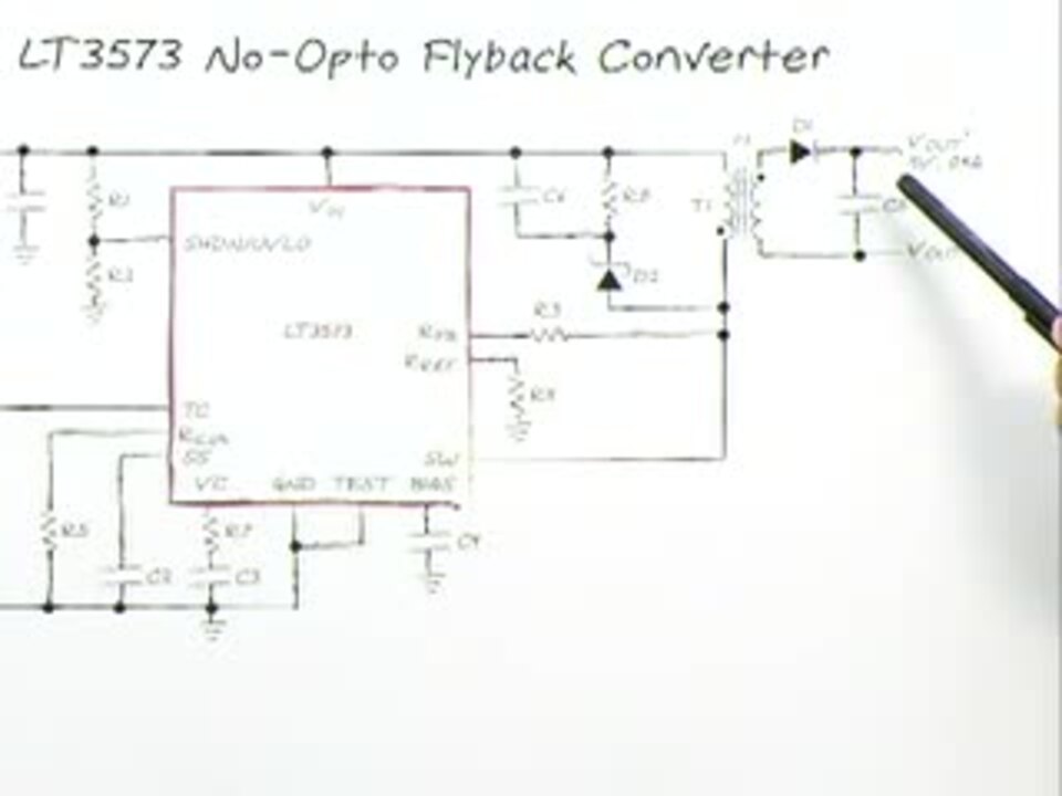
Linear Technology also supplies a monolithic switching voltage regulator specifically designed for isolated flyback topology. The LT3573 integrates an NPN power switch along with all control logic into a 16-lead MSOP package. The chip operates with input supply voltages from 3 to 40 V, and can deliver output power up to 7 W with no external power devices. Figure 3 shows the efficiency curve for the chip which peaks at 78 percent for an input voltage of 24 V, output voltage of 5 V, and an output current of 800 mA.

Figure 3: Efficiency curve for Linear Technology's LT3573 configured as a 5 V output flyback regulator.
From the flyback regulator schematic in Figure 2 it can be seen that the transformer is an external component, because it is (obviously) too big and bulky to be integrated into a chip. This could be regarded as an inconvenience, but is no more so than the requirement for an inductor in a conventional buck/boost regulator topology (except in a few cases where the inductor is integrated into the module, see the TechZone article "Design Trade-offs in Integrating an Inductor into a Power Module").
It turns out that the transformer is the key component in a flyback design and needs to meet a number of key performance characteristics to ensure good performance from the regulator.
First, the transformer needs to be of sufficient inductance to operate in a continuous conduction mode over a wide load range. Moreover, a high-inductance transformer will dampen the ripple currents that can otherwise plague the primary and secondary circuits.
Second, the transformer should be as compact as possible while still meeting the other performance criteria. A smaller transformer uses less ferrite material, will be less expensive, and will also occupy less circuit board real estate.
Third, a rule of thumb is that the transformer dissipation (core and winding losses) should be limited to less than three percent of the total power. Designers should use copper windings comprising multiple strands of thin wires — with a diameter not greater than twice the copper's skin effect depth at the switching frequency — to minimize winding losses.
The alternative to constructing a transformer is to consider one of the many off-the-shelf devices available to provide single positive, or dual positive and negative output voltages, from manufacturers such as Würth Electronics (Figure 4).

Figure 4: Würth Electronics makes a range of transformers suitable for flyback regulators.
Engineers wanting to experiment with flyback regulators can obtain evaluation kits that allow testing of prototype designs. National Semiconductor products from TI, for example, include a flyback regulator evaluation kit, the LM5020EVAL, based on the company's LM5020 switching controller.
In summary, the flyback regulator is a good choice of technology for designs that require a switching buck/boost DC/DC regulator that can handle high voltages with isolation for safe operation. Flyback regulators are best suited to relatively low power operation (below 50 W) and careful design/selection of the output transformer is required to keep down cost, limit product dimensions, and dampen output voltage- and current-ripple.
References:
- "Flyback converter," Powerwise Design University Team, National Semiconductor, 2010.
免责声明:各个作者和/或论坛参与者在本网站发表的观点、看法和意见不代表 DigiKey 的观点、看法和意见,也不代表 DigiKey 官方政策。