Airflow Sensors Assure Reliable Cooling
投稿人:电子产品
2012-10-25
Heat can be the great enemy of more than just electronics. Modern day refrigeration and cooling systems are multi-billion dollar industries whose products not only keep us cool and comfortable, but also keep food from spoiling, medicine from going bad, and internet servers at temperatures that keep them functioning.
While temperature sensors do a good job of monitoring the amount of heat in an enclosure or on a surface, they cannot bring about any change in temperature. That task falls to sensing and control systems using active and passive cooling techniques.
Liquid cooling is a well-established technology, but it is unnecessary and/ or cost prohibitive in most electronic applications. Heat sinks do a good job when conditions stay within a predefined window of extremes. In the middle are airflow systems that often provide the best cost/performance solution when heat is the enemy.
This article discusses airflow sensors and how they can be used in systems that control, monitor, test, and calibrate for dynamic temperature compensation. The parts, data sheets, development systems, and training materials mentioned here are available online at Digi-Key’s website.
How it works
Airflow generators, such as muffin and squirrel cage blower assemblies, typically have tachometer outputs that can be used to assure a control system that the fans are turning. This is a good verification and should be used as part of the system integrity check routines. Still, a turning fan is no guarantee of airflow. Clogged ducts and passages can constrict or even stop airflow. This is where sensors make a difference.
Airflow sensors are typically based on switches, paddles and diaphragms. Switches basically detect a pressure set and release point and should exhibit a certain degree of hysteresis to simplify the control logic’s job. Paddle wheels are just that, wheels or cages that turn like a fan in the wind to generate a signal level corresponding to the rated airflow. Diaphragms can operate as switches, or as linear sense elements depending on how they are constructed.
The simplest and most cost effective airflow sensors are designed to trip a switch closure at a specified minimum air pressure and release the switch at another specified pressure level. These digital ‘on’ and ‘off’ switches can be used to quickly verify airflow is present.
Note that low-cost and non-mission critical applications will most likely make their own pressure trip switches. Any low cost mechanical switch specified within a tolerable range of closure force accuracy can be used in a mechanical assembly (Figure 1). Bounce vibration sensitivity and hysteresis are issues your design team will need to solve, but this approach can result in a good, reliable and cost-effective solution.
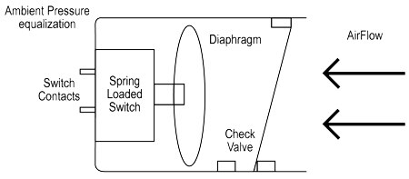
In a medical application, factory, or military design, on the other hand, where well-engineered components are certified to demanding specifications, a more refined sensor or assembly is necessary.
Take for example the Honeywell 76064-00000600-01 pressure switch, which features non-ferrous chambers for corrosion avoidance. The Honeywell family members range from 20 PSI to 3000 PSI set points. Sealed to IP65 specifications, these pressure switches can withstand reactive gases as well as liquids ranging from oxygen to brake fluid.
It should be pointed out that vacuum sensing technology can also be employed to sense airflow when a Buchner Funnel approach is used (Figure 2). Here, the presence of airflow draws air (or fluid) out from an angled path to create a vacuum that can be connected to a switch closure.
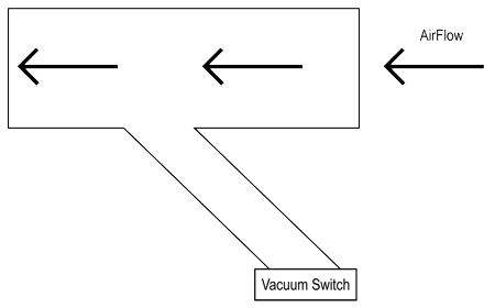
A case in point is the Honeywell 77343-04.0HG-01 vacuum switch. This looks identical to the company’s pressure switches and works the same way, except that it switches when a set point of vacuum is obtained (Figure 3).
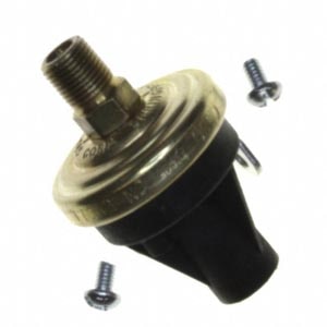
Outputs from these types of sensors are dry contacts that can be N.O. or N.C. SPST or SPDT types of contacts in a variety of platings, including silver for very low resistance and gold for non-oxidizing applications.
A good overview can be found in the company’s Pressure Switches Line Guide, which presents the specifics of the diaphragm materials, set point ranges, hold and release pressure (hysteresis), and more.¹
Clean air sensors
A large percentage of designs will not expose the sensors to any out of the ordinary substances or physical abuse. Server farms, for example, can generate a lot of heat, but are in enclosed areas with fairly good air quality and temperature control. In these cases, you may want to look at D6F airflow sensors and assemblies from Omron.
The D6F family includes a variety of form factors and capabilities under this umbrella classification. Notable for its compact and patented technology, this family is capable of measuring flow velocity and mass flow rate movement with highly repeatable accuracy from 1 LPM to 50 LPM (Liters per Minute).
Also worth a look is the Omron D6F-P0001A1 MEMs flow sensor (Figure 4). This part measures a tight range from 0 to .1 Liters per minute of airflow, which makes it a fairly sensitive device. The D6F-P0010A2 is a similar part with a 0 to 1 Liter per minute range.
A particularly nice feature of the Omron D6F family is its dust segregation system, which allows these parts to be used to monitor the performance of fans and detect clogged filters for computers or projectors, for example.

It is interesting to note that the output from these sensors is an analog voltage (Figure 5). As a result, instead of just a dry contact switch, the performance curve can be used to not only verify airflow, but also to measure it.
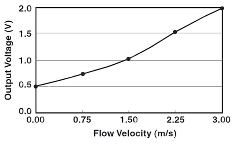
This opens the door for low power applications that need to stay cool, but want to limit the amount of energy sent to a blower motor. Here, an algorithm can be developed that optimizes energy use by using a variable speed blower control and measuring temperature and airflow.
Omron offers training on MEMs Flow Sensors which can provide useful information when either just starting out with flow rate sensing, or, keeping up to date with the products and technologies available to you.
High flow rates
In the same way as adding a parallel resistor to an ammeter to increase its measurement range, airflow sensors can be used in a shunt configuration allowing them to measure higher volumes of airflow. While this extends the range of measurement, it can also cause a multiplication of accuracy error since the resolution of the sensor is now extended to the higher range.
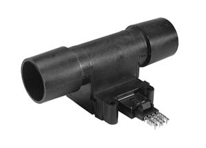
Alternatively, you can use a sensor designed to handle higher levels of airflow such as the Honeywell AWM720P1 Mass Airflow Sensor (Figure 6). Designed for medical applications, this part can also be used for analytical instrumentation, fuel cell control, telecommunications systems, and to measure in line flows as high as 200 standard liters per minute, with a low 1-inch H²O of pressure penalty.
This part also has built in sensor amplification and temperature compensation to help assure long term stability. It features a nice 5 Volt peak analog voltage curve corresponding to the airflow rate.
There are also hand-held airflow sensors to consider; inside a cabinet, for example, you may think you have airflow in the needed places, but when everything is sealed up, you can’t know for sure.
A good example is the B&K Precision 731A wand based anemometer. This useful tool records min and max and averaging of airflow and can perform multipoint averaging as well in 2-second and 16-second time-blocks.
Summary
Modern temperature sensors let you know when temperatures are within an acceptable range. Tachometers on blower motors let you know the fans are turning. But airflow-based cooling is the well-established, cost-effective and proven way of extending the operating temperature of electronics exposed to heat. (It also removes the heat that electronics themselves can generate.) In sum, airflow sensors tie it all together to assure the control processor that your cooling system is working properly.
References
免责声明:各个作者和/或论坛参与者在本网站发表的观点、看法和意见不代表 DigiKey 的观点、看法和意见,也不代表 DigiKey 官方政策。


