A Designer's Guide to RFID
投稿人:Convergence Promotions LLC
2013-05-02
One of the most influential trends in 21st century electronics is communications via wireless methods. Tablets, smartphones, and their ilk get the glamour, but much of the heavy lifting is being done by enormous numbers of radio frequency identification devices (RFID).
RFID is a way to communicate very short distances, very cheaply at low data rates. It has been used to track packages for toll collection on highways, for inventory management, and more. The item being tracked is called a "tag" and nearly always requires no battery or other power source, which differentiates RFID from all other wireless communications schemes.
RFID provides a non-contact way of collecting information about a product or device. In general, the transponders (or "tags") cost little – often under a dollar – and can therefore be more or less disposable. Libraries use tags to track individual books. Wal-Mart has attempted to tag virtually everything they sell for better inventory management. Tags can be used in harsh and dirty environments not conducive to bar codes or other techniques.
RFID is difficult to pin down as the term encompasses a wide range of device types and frequencies. The E-ZPass® automated toll collection system used in the USA's Northeast, for instance, uses RFID transponders operating at 915 MHz. Other bands in the GHz range are available as well.
But nearly all RFID work is done in two lower-frequency bands: 13.56 MHz and (approximately) 125 KHz. Unlike the shorter-wavelength bands, 13.56 and 125 KHz are authorized for these applications in just about every country.
RFID is further confused by the types of units. Active transponders have a battery and work very much like a traditional radio. Battery-assisted units, which are not particularly common outside of key fobs, may do some energy harvesting but require some source of power.
Passive units are the most common; a passive unit has no battery and does not use mains power. A passive tag harvests energy from the applied electromagnetic field created by a reader (see Figure 1).
Passive tags are further subdivided into read-only and read-write varieties. The former have pre-programmed IDs which are used mostly for tracking items and the latter can store some information, somewhat like a web-browsing cookie.
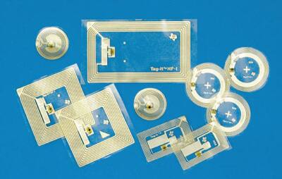
Figure 1: Typical passive tags.
There is a common misconception that passive read-only RFID tags are simply antennas that interact with the field. The truth is that every tag has an IC that stores the ID and manages communications.
Typically 125 KHz units have a range of a few centimeters; at 13.56 MHz that increases to a meter or two, depending on antenna size and some other factors.
Data rates vary. An LF unit will max out around 4 kbits/sec, while a 13.56 MHz device can support speeds to 800 kbits/sec. These are not sustained rates since each has some charge time associated with it (described later in this article).
Systems include the tag itself, an associated antenna, and a reader (with its own antenna) that creates the field and communicates with the tag. Some vendors sell tags as complete units with the antenna. An example is shown in Figure 2. It is a self-enclosed glass tag from Texas Instruments and is available in both read-only and read-write versions.
Figure 2: Texas Instruments’ 23 mm glass tag (Courtesy of Texas Instruments).
There are a lot of acronyms and unique names used in this area:
- RFID: Radio frequency identification
- Reader: Also sometimes called an interrogator or vicinity coupling device (VCD)
- Tag: The mass-produced transponder
- LF: Low frequency, or 125 KHz (approximately)
- HF: High frequency, or 13.56 MHz
- NFC: Near-field communication
- NDEF: Near-field data exchange – the process of communicating with a tag
- EPC: Electronic product code. The ID stored in a tag.
A passive tag harvests the energy it needs from an electromagnetic field created by the reader. As illustrated in Figure 3, the reader feeds the "antenna" (really more of a coil than a conventional antenna) an oscillating signal – thanks to Maxwell's Laws that field couples to the tag's antenna (again a coil). The signal is rectified and charges a small capacitor which powers the tag.
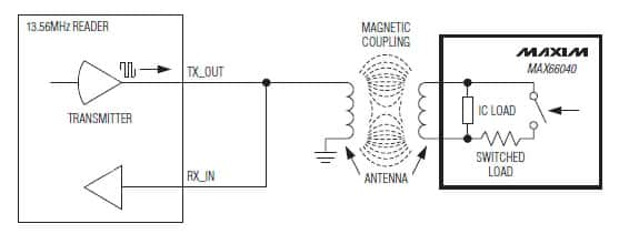
Figure 3: Typical arrangement between reader and tag (Courtesy of Maxim).
Tags are usually dead – totally unpowered and not in any sort of sleep mode unless interacting with a reader. When the reader initiates a data exchange it first drives the antenna for, typically, 15 to 50 msec. That excites the resonant circuit on the tag and charges the capacitor.
Data is exchanged using backscatter modulation. As the tag switches a load on and off, the reader's antenna experiences a change in voltage. Think of the two coupled antennas as a transformer: drop a load on the secondary and that affects the primary winding.
Either frequency-shift or phase-shift keying it used, and on 13.56 MHz devices two or more subcarriers may be employed. The details are surprisingly complex for such low-cost devices, but happily they are completely managed by the tag and reader ICs; the design engineer will not be exposed to those aspects.
Antennas
A critical part of designing the reader is creating an antenna which will most efficiently carry a signal to/from the tag. While commercial antennas can be used, they are expensive. It is common to build one using PCB tracks to form a loop.
The range of a tag is influenced by:
- The size of a tag’s antenna. The larger the tag’s antenna the stronger the response and the better the tag can be detected above the background noise.
- The size of the reader’s antenna. A larger reader antenna increases the read range, but in a noisy environment it may have a worse signal-to-noise ratio and cause the reading distance to go down.
- The orientation of antenna.
- The match of the LC formed by the antenna and stray (or intended) capacitances.
- Environmental noise. The tag has to have a 6 dB stronger signal so that the reader can distinguish it from the background noise. As noise increases the tag has to move closer and closer to the reader’s antenna to be detected.
- The antenna's Q factor. Generally a Q between 30 and 40 is needed.
Capacitance is encountered in the reader IC and can range from 20 pF to ten times that value, but the datasheet will give the appropriate number. Especially for devices with low C values, it is important to figure in any parasitics from track coupling or wires to an off-board antenna.
Maximum energy transfer occurs when the antenna and associated components are in resonance. That happens when the reactance of the inductor is equal to that of the capacitances. Capacitive reactance is:

where f is the frequency (125 KHz or 13.56 MHz) and C is in Farads.
Inductive reactance is just the opposite:

(L is in Henries).
Measure the inductance of the antenna with an LCR meter. Setting the two equations equal (since the reactances are the same at resonance) and solving for C:

C is the total capacitance of the antenna system, which will be that of the reader IC (from the datasheet), parasitics (if any), and that of a capacitor placed in series with the antenna to get the two reactances to match. If CIC is that of the IC, and CC is the value of the compensating capacitor added in series, then:

So:

(More detail can be found here.)
Readers
A reader can be a pretty complex device depending on its intended application. One might just simply push data from RFID tags to another computer for inventory management; another may require a display and keyboard with a wireless connection to an accounting computer.
All modern RFID reader ICs take care of the entire RF front-end (excepting the antenna) and handle all of the modulation and message passing. The IC's interface is entirely digital using a conventional parallel or serial bus.
Texas Instruments’ TRF7970ARHBT, whose block diagram is shown in Figure 4, is a typical reader IC.
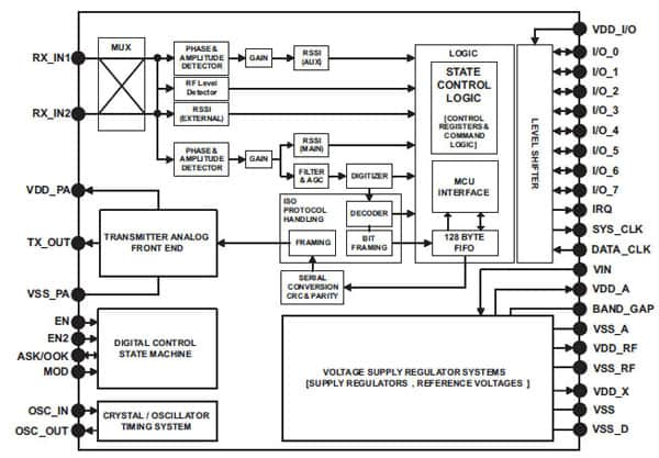
Figure 4: Texas Instruments TRF7970ARHBT block diagram (Courtesy of Texas Instruments).
Unlike some other devices, the TRF7979ARHBT does provide access to analog/RF front end (via digital command sets) letting the user create custom, non-standard, communications protocols.
The part includes signal strength measurements as well as a programmable power level to the RF front-end. An application can use these features to communicate at low power to maximize battery life in portable applications, but it can dynamically boost the RF levels if the tag's signal is weak.
That brings up an important point. The power level into the antenna of a reader is highly dependent on supply voltage. In the case of this part, a five volt supply supports levels up to 200 mW; at three volts that is reduced to 70 mW, shortening the reader's range.
NXP Semiconductor's HTRC11001T is another reader IC. At 14 pins it is smaller than the previously-mentioned Texas Instrument’s part, as well as cheaper; the pin-count reduction is driven in part by the use of an SPI interface to the rest of the system.
Like many of these devices, it will automatically detect a short-circuited or open antenna. It is checked every cycle of a transmission; it is up to the code in the processor that is controlling it to shut down transmission to keep the device from failing. Idle and power-down modes can drop quiescent current to under 20 μA. This is a very simple device to use. Figure 5 shows a typical application.
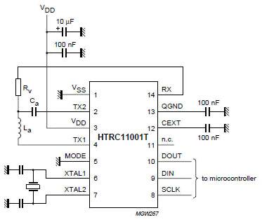
Figure 5: Using the HTRC101T (Courtesy of NXP Semiconductors).
Tags
Tags are most often used as simple data storage devices. The reader extracts a tag's unique ID to track packages and the like. Or it could write information (in a read/write tag, of course). The EZ-Path® toll transponders are sometimes used this way; authorities can have the toll booth write where a car entered a highway to compute tariffs based on distance traveled. All tags used just for data storage come as assembled units rather than as ICs. An example is the cylindrical glass unit described earlier.
The critical specification for any tag is the memory size. Read-only devices typically can store a 64- or 80-bit unique number that is written by the factory. Read/write versions will have anywhere from 256 bits of user-memory up to tens of thousands of bytes.
Read/write transponders will always have a command set used to control store and read data. Generally the command set is very simple: read, write, and announce your ID. Some include a kill, which causes the tag to go inactive forever as a security precaution.
TI has an entire line of "inlays" – tags that are complete with an antenna on a flexible sheet of plastic. The Tag-it™ series has several hundred different devices with varying physical configurations (round, square and rectangular) and memory of 256 or 2 kbits. An example is Texas Instruments’ RI-I16-114A-S1, a circular unit as shown in Figure 6.
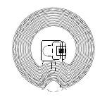
Figure 6: One member of Texas Instruments’ Tag-it family (Courtesy of Texas Instruments).
But there is another use for RFID transponders. Consider a tire pressure monitor. Though the IC is the reader half of the system, there is also a tag in each wheel. This is an example of an application where the tag IC is tied to a microprocessor that reads a sensor. A typical block diagram for this sort of application is shown in Figure 7.
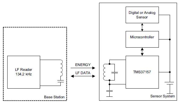
Figure 7: A tag that talks to a local microprocessor (Courtesy of Texas Instruments).
But wait! What powers the CPU?
The RF field does. Figure 7 shows Texas Instruments’ TMS37157 transponder IC supplying power to the attached controller. This part can be used in battery-powered systems, of course, but it has a VBAT output that sends power harvested from the field to the MCU. Not much is available – no more than 16 mA, and then only in a strong field. Also the processor will be dead when there is no active reader nearby, so the code has to deal with a sudden wake up and just as quick death; RAM contents will be lost. But the TMS37157 has 121 bytes of EEPROM in which the CPU can store state data.
STMicroelectronics sells transponder ICs but calls them EEPROMs. An example is the M24LR16E-R, which is sort of a hermaphrodite. It can be used as a conventional RFID tag, but it also has an I²C output that connects to a processor; in the latter mode it will need power from a battery or other source. Its 2 KB of memory can be password-protected in 512 byte blocks.
Development support
Most vendors have development kits and boards to support prototyping. Texas Instruments’ TRF7970A evaluation module, shown in Figure 8, lets the user experiment with all of the TRF7970A's commands.
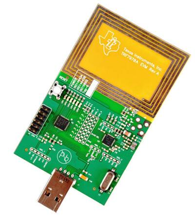
Figure 8: TRF7970A evaluation module (Courtesy of Texas Instruments).
It connects to the PC via USB and has a custom GUI to control the board, as shown in Figure 9.
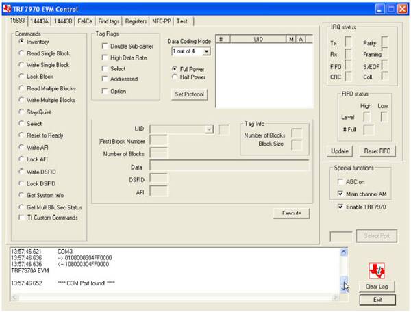
Figure 9: TRF7970A GUI.
For low-volume products, readers are available as subassemblies. Texas Instruments’ RI-RFM-003 is a reasonably-priced module that communicates with a host computer using a proprietary interface.
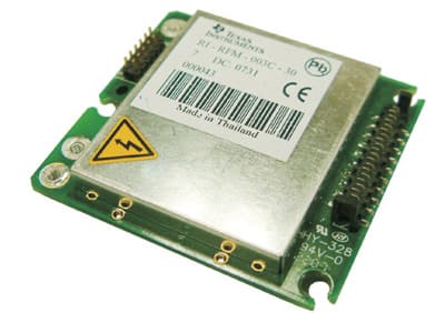
Figure 10: Texas Instruments’ RI-RFM-003C (Courtesy of Texas Instruments).
DLP Design makes a similar reader, the DFP-RFID1 which communicates via USB (see Figure 11).
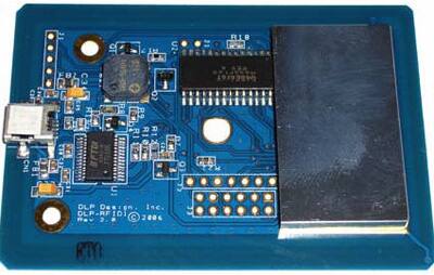
Figure 11: DLP Design's DLP-RFID1 reader (Courtesy of DLP Designs).
Conclusion
Today we are faced with a huge number of wireless ways to transmit data: Bluetooth®, Wi-Fi®, WiMAX®, and more. RFID is a logical choice for many applications where distances are very small and batteries not desired. The costs can be trivial and development effort low.

免责声明:各个作者和/或论坛参与者在本网站发表的观点、看法和意见不代表 DigiKey 的观点、看法和意见,也不代表 DigiKey 官方政策。


