ZigBee Evaluation Kit Supports 2 x 2 MIMO
投稿人:Convergence Promotions LLC
2013-04-18
With machine-to-machine (M2M) applications growing at an exponential rate, the race is on to see which wireless protocols come to dominate this space. As always, the solution depends on the problem. For long-distance, wireless 2G cellular might best fit the bill. For shorter wireless distances Wi-Fi®, Bluetooth®, and a number of 802.15.4-based protocols – ZigBee being chief among them – can all work. However, if your intended application needs to be ultra-low-power but work in an environment where link reliability may be a problem, Atmel’s 2.4 GHz REB233SMAD Evaluation Kit (see Figure 1) deserves a look.

The REB233SMAD-EK contains two radio extender boards (REB) based on the Atmel AT86RF233 2.4 GHz RF transceiver; two controller base boards (CBB) built around the ATxmega256A3 MCU; two USB adaptors with cables for programming the MCU; four SMA antennas; plus batteries and a Quick Start Guide. The wireless boards plug into the MCU boards, enabling you to do an immediate range test of two complete wireless nodes using a simple ready to run range measurement application.
The kit is designed to be a complete platform for designing and prototyping ZigBee-compliant wireless applications such as ZigBee SmartEnergy and Home Automation systems. To that end, Atmel supplies its BitCloud™ stack – a ZigBee® PRO certified platform – and the BitCloud Profile Suite.
Controller base board
The controller base board (REB-CBB) is built around an 8-bit Atmel AVR ATxmega256A3 MCU. The board has a connector for programming and debugging using an Atmel AVR JTAGICE programmer.
The ATxmega256A3-AU used in this kit (see Figure 2) is a low power, high-performance 8/16-bit MCU that runs at 32 MIPS at 32 MHz. It has 256 KB of programmable Flash program memory, 8 KB of data Flash, 4 KB of EEPROM and 16 KB of SRAM. Peripherals include a 4-channel DMA controller; an 8-channel event system; seven 16-bit timers/counters; seven UARTs; two 8-channel 12-bit, 2 MSPS ADCs; one 2-channel, 12-bit, 1 MSPS DAC; and a programmable multi-level interrupt controller.
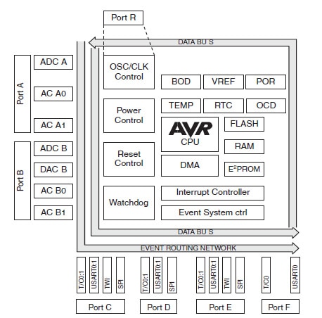
Figure 2: AVRxmegaA3 block diagram. (Courtesy of Atmel.)
To keep power consumption down, the chip has five sleep modes: idle, power-down, standby, power-save, and extended standby. In Active mode (32 MHz VCC = 3.0 V), the chip typically draws 15.7 mA; in Idle mode, 6.89 mA; power down (ULP, WDT, Sampled BOD), 1 μA; power-save (RTC 1 kHz), 0.7 μA; and extended standby (all functions disabled), 0.1 μA. Needless to say, the Active mode current scales back quickly with a drop in clock rate (71 μA at 32 kHz).
For more information on this and other Atmel MCUs check out their MCU Product Line Introduction training module.
Radio Extender Board
The radio extender board (REB) is built around a 2.4 GHz Atmel AT86RF233 transceiver chip that is targeted for IEEE 802.15.4, ZigBee, RF4CE, 6LoPAN, and ISM applications.
With the addition of just a few external components – all of which are included on the board (see Figure 3) – the AT86RF233 forms a complete FCC Part 15-certified RF front-end module.
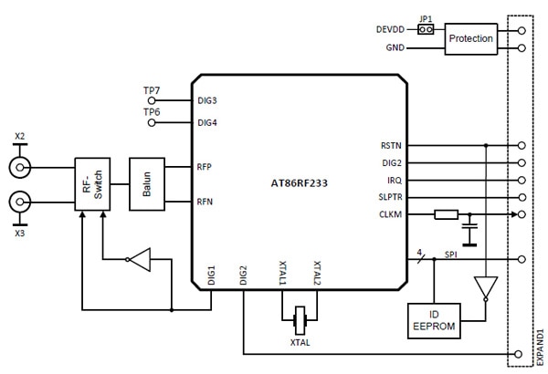
The board has two SMA connectors to support antenna diversity. While in receive mode, the chip continuously switches between the two antennas to select the one providing the best receiving path. Once an IEEE 802.15.4 synchronization header is detected, the antenna providing the better signal quality receives the rest of the frame. This can greatly increase reliability when the signal link suffers from noise or multipath fading.
In receive mode, the AT86RF233 draws 11.8 mA, with a listen mode that can further reduce current consumption by 10 to 50 percent. Receive sensitivity is -101 dBm for a data rate of 250 Kbps and a packet error rate (PER) of less than or equal to one percent; this reduces to -88 DBM for a maximum data rate of 2000 Kbps for non-IEEE 802.15.4 networks. The noise figure is 6 dB and adjacent channel rejection is 35 dB (+5 MHz, PRF = -82 dBm).
In transmit mode, the AT86RF233’s current consumption varies with the output power, which is programmable from -17 dBm (7.2 mA) up to +4 dBm (13.8 mA). With the transmitter turned off (IGTRX_OFF), current consumption drops to 300 μA. In sleep mode, the chip draws only 0.2 μA; and in deep sleep mode, this drops further to 0.02 μA. The chip lives up to Atmel’s claim for being ultra-low-power.
Despite being low power, the chip is not lacking in features. It includes an integrated, fast settling PLL to support frequency hopping with 500 kHz channel spacing. IEEE 802.15.4-2011 support includes frame check sequence (FCS) computation, clear channel assessment, RSSI measurement, energy detection, and link quality indication. The transmit modulation scheme is offset QPSK (O-QPSK) with half sine pulse shaping and 32-length block coding (spreading). Security features include a 128-bit AES engine with true random number generation for security applications.
Atmel makes other numerous wireless chips. For further information, check out the Wireless Solutions Product Line Introduction training module on DigiKey’s site.
Range check
The REB233SMAD comes with a pre-flashed range measurement application that I was able to start using within a few minutes of opening the box. Getting started simply involves plugging the radio cards into the baseboards; plugging the antennas into the radio cards; plugging the supplied AAA batteries onto the baseboards, and turning on both baseboards.
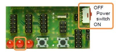
When I turned on the power switch, the middle of three LEDs lit up indicating successful program initialization (see Figure 4). Pressing button T1 starts the application. LED-D2 blinking indicates successful transmission and LED-D3 successful reception.
I turned on both boards and put one into transmit mode and let the other act just as a receiver. For the range test, I started the program on both boards for full duplex operation. The 2.4 GHz kits I have tested before were usually lucky to transmit across our (not very large) house. This kit showed no signs of dropping packets, so I took it outdoors and resorted to my traditional range test platform (see Figure 5).
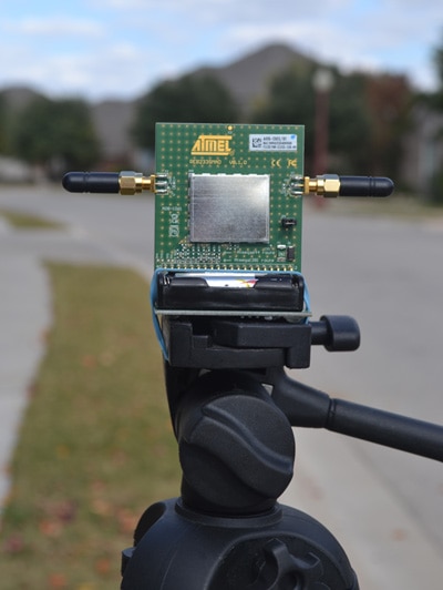
Having received only two of the larger, hinged antennas that come with the kit, I instead used four matching ¼-wave stub antennas. Repeated tests showed the effective range to be about 350 feet. Substituting the larger antennas at one end increased the range to about 500 feet. That is about ten times farther than I have been able to get even with a range extender at home at the same frequency using Wi-Fi. The combination of high receiver sensitivity and antenna diversity – not to mention a low-data rate protocol – definitely gets the job done.
Packet error-rate measurement
The same program that enables quick range check also allows for packet error rate (PER) measurement, as well as adjusting different transceiver features. To do this, connect one of the USB adapters supplied with the kit to the board and then plug it into your PC, having first downloaded the drivers for the adapter. You can then start a UART terminal program (9600, N,8,1) and point it at the proper port. You can then configure the transceiver and perform various service functions. While the PER program could benefit from a GUI, it is still quite capable and enables you to experiment with numerous features and parameters.
Antenna diversity
The most interesting feature of the AT86RF233 is its built-in support for antenna diversity – in this case, 2 x 2 MIMO – which can significantly improve network reliability without increasing the link budget – that is, without using a higher transmit power or an additional low noise amplifier (LNA) ahead of the receiver.
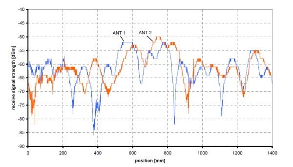
With the introduction of multipath fading between two network nodes, the signal arriving at each of the dual antennas on the transceiver board can vary considerably over time. Without antenna diversity, these fading effects could quickly result in an increased error floor or loss of the connection between network nodes. Figure 6 shows typical receive levels for each antenna on the REB233SMAD’s radio extender board (REB) in a multipath fading scenario. Switching between antennas and selecting one that receives better increases the reliability of the connection. The AT86RF233 does this continuously and automatically.
The two matching ¼-wave antennas on the REB connect to an RF switch and a balun (see Figure 7). The RF switch in turn is controlled by DIG1/2 on the AT86RF233.
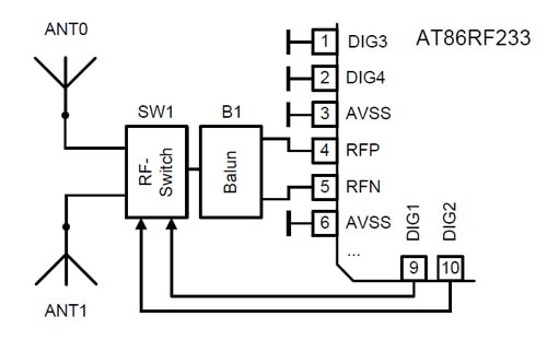
Figure 7: Antenna diversity using the AT86RF233. (Courtesy of Atmel.)
Receive Diversity
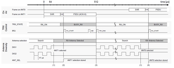
If antenna diversity is turned on (see Figure 8), the transceiver continuously switches between the two antennas while searching for an IEEE 802.15.4 synchronization header (SHR). When a sufficiently strong SHR is detected (Figure 8 (1)), that antenna locks on (Figure 8 (2)) to receive the PHY header (PHR) and the PHY Service Data Unit (PSDU). Upon receipt of a complete frame, the search then continues (Figure 8 (3)) until a new SHR header is detected or the receive state is terminated for whatever reason.
Transmit Diversity
Upon successful reception of a PHY header (see Figure 9 (1)), the transmit antenna may be automatically selected (RX_START), though this is best left until after it has been determined that the frame has a valid FCS (Figure 9 (2)). An acknowledgement frame (RX_AACK) is sent after a predetermined turnaround time (Figure 9 (3)).
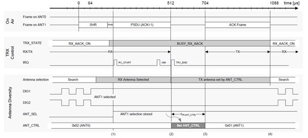
The selected antenna will depend on the results of the last data exchange, or you can choose to permanently use one antenna for the receiver and the other for the transmitter. When using the antenna diversity algorithm to select antennas, you will need to fine tune the receive threshold to reflect the realities of the local RF environment.
Summary
Low-power wireless networks are enabling a wide range of commercial, industrial, medical, and security applications. M2M applications in particular are a wide-open field for ZigBee and other 802.11.5-based protocols. All such applications could benefit from the increased signal reliability from antenna diversity.
Designers considering such applications would do well to check out Atmel’s REB233SMAD-EK Evaluation Kit, which provides a high-performance platform for both design and development of low-power wireless networks.

免责声明:各个作者和/或论坛参与者在本网站发表的观点、看法和意见不代表 DigiKey 的观点、看法和意见,也不代表 DigiKey 官方政策。


