What's New and Notable in Inertial Sensors
投稿人:电子产品
2012-11-29
Most of the growth in inertial sensor use is based on advances in MEMS technology that enable these devices to detect and measure acceleration, tilt, shock, vibration, rotation, and multiple degrees-of-freedom (DoF) motion. Formerly relegated to navigation applications where their high price tag could be justified, today’s inertial sensors play a role in industrial, communications, automotive, medical, and consumer applications.
In a recent Status of the MEMS Industry 2012 report, GII and Yole Developpement reported that MEMS sensors will continue to see steady and sustainable double-digit growth for the next half dozen years, with 20 percent compound average annual growth (CAGR) in units and 13 percent growth in revenues.
They estimate that accelerometers, gyros, magnetometers and combinations will account for approximately 25 percent of the total. Yole also broke out a separate category for combo sensors, showing that the market for discrete inertial sensors will begin to decline, but the growth for inertial combo solutions will be huge, moving from its current less than $100 million to a whopping $1.7 billion by 2017.
So, what is behind this growth spurt? The answer involves size, power, intelligence, and cost.
First, though, let’s do a quick review of what constitutes an inertial sensor. Inertial sensors involve measurement without an external reference. For example, accelerometers measure specific force and gyroscopes measure angular rate. If they measure force or angular rate that is relative to environmental features, they are not inertial-sensor devices.
Inertial measurement units (IMUs) are sensor packages containing multiple accelerometers and gyroscopes, and are used to produce 3D measurements of specific force and angular rate. Inertial navigation systems (INS) comprise computers, accelerometers, and gyroscopes that calculate using dead reckoning position, orientation, and velocity of an object in motion – again, without external references.
Exploding applications areas include automotive, consumer and medical segments. In the automotive realm they are used for ABS, electronic stability control to handle skidding and recovery, roll stability for high-center-of-gravity vehicles, and anti-theft systems involving towing or jacking up a vehicle. Consumer uses have blossomed, too, especially in the mobile phone, tablet, and game segments. These designs require commodity pricing, extreme miniaturization, low power, and multi-axis sensor design compared with heavy-duty high-performance automotive and medical requirements. Medical applications include instrumentation, pacemakers, and patient monitoring.
All of these emerging uses are taking place alongside traditional navigation applications. Typically, a highly accurate navigation system using inertial sensors employed fiber optic gyroscopes (FOG) or ring-laser gyroscope (RLG) technology. Both solutions, while accurate, are definitely expensive. MEMS-based systems are taking hold in markets where the aforementioned technologies could not be considered based on their price tags, or on a lower requirement for accuracy.
How accurate are the technologies when compared? Switching from FOG systems to MEMS navigation systems yields an impressive 20x accuracy and reliability improvement, combined with an ability to withstand vibration. MEMS win in such applications as unmanned aerial and ground vehicles, precision agriculture control, in-dash vehicle navigation systems, antenna array stabilization systems on moving platforms, earthworks, and mining navigation and safety.
In navigation, MEMS has gained favor more recently due to improvements in error characteristics, environmental stability, high bandwidth, and the computational power that can run advanced fusion and sensor error modeling algorithms which were previously unavailable.
MEMS-based inertial sensors offer such characteristics as miniaturization and 6-axis devices – some with footprints down to 3 mm x 3 mm x 1mm. They can deal with space constraints, the power-hungry nature of portable designs, and the increased number of lower-priced applications in sports, fitness, and healthcare.
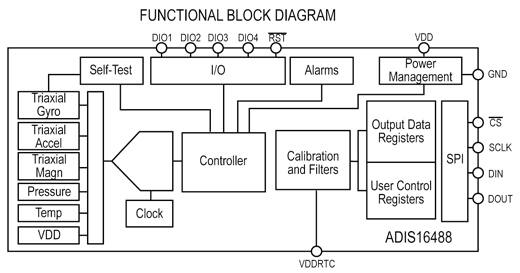
Consider, for example, the ADIS16488 iSensor inertial measurement unit (IMU) device from Analog Devices. Available in an evaluation board, this is a complete inertial system that includes a tri-axis gyroscope, a tri-axis accelerometer, tri-axis magnetometer and pressure sensor. Each inertial sensor in the ADIS16488 solution combines iMEMS technology with signal conditioning that optimizes dynamic performance. Factory calibration characterizes each sensor for sensitivity, bias, alignment, and linear acceleration (gyroscope bias), and each sensor has its own dynamic compensation formulas for accurate sensor measurements.
The ADIS16488 (Figure 1) is a cost-effective way to integrate accurate, multi-axis inertial sensing into industrial systems. Motion testing and calibration are undertaken at the factory, reducing integration time. Tight orthogonal alignment simplifies inertial frame alignment in navigation systems. Within this industrial environment, the IMU can be used for platform stabilization and control, navigation, personnel tracking, robotics, and instrumentation.

In comparison, STMicroelectronics’ MEMS iNEMO inertial module enhances the user’s experience along with motion-sensing realism in space-constrained and power-hungry portable consumer devices. It is also used for wearable sensor applications in sports, fitness, and healthcare diagnostics.
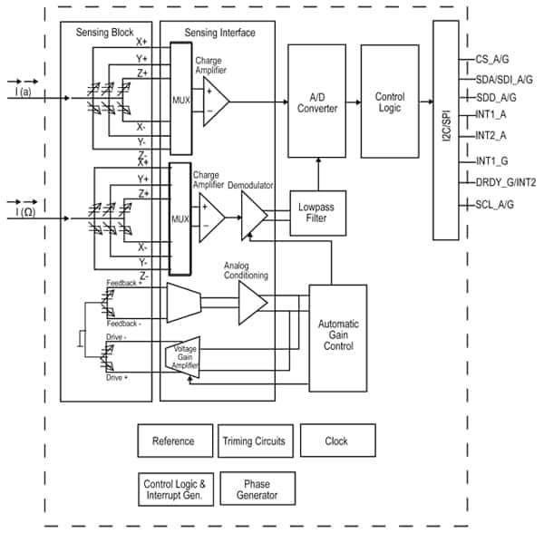
The LSM330 module houses a three-axis digital gyroscope and a tri-axis digital accelerometer with two embedded finite state machines – programmable blocks that allow custom motion recognition inside the module. Programmable state machines enable the ID of specific motions or gestures and resulting associated actions, such as switching on an augmented-reality view of a nearby object by moving a phone with a specific gesture. The module targets a wide range of applications that also include wearable sensors, motion-activated user interfaces in phones and tablets; motion detection and map-matching for indoor/outdoor navigation, augmented reality, and location-based services.
Specifically, the LSM330DLC (Figure 2) is a system-in-package featuring a 3D digital accelerometer and a 3D digital gyroscope. It has a dynamically user selectable full scale acceleration range of ±2 g /±4 g /±8 g /±16 g and angular rate of ±250/±500/±2,000° per second. The accelerometer and gyroscope sensors can be activated or separately put in low power/power-down mode for applications where power saving is important. Applications include GPS navigation, impact recognition and logging, gaming and virtual reality input, motion activated functions, intelligent power saving for handhelds, vibration monitoring and compensation, free-fall detection, and 6D orientation detection.

Features include:
- Analog supply voltage: 2.4 V to 3.6 V
- Digital supply voltage IOs: 1.8 V
- Three independent acceleration channels and three angular rate channels
- SPI/I2C serial interface (16-bit data output)
- Programmable interrupt generator for free-fall and motion detection
- ECOPACK RoHS and “Green” compliant
More interesting inertial sensor applications are certain to come. For example, an MIT team recently built a camera-free plane that autonomously navigated through tight indoor spaces using onboard sensors only. The plane does not require a pilot, remote control, or a GPS.
At the 2011 International Conference on Robotics and Automation (ICRA), the team of MIT researchers described an algorithm for calculating a plane’s trajectory. In 2012, at the same conference, they presented an algorithm for determining its “state” – its location, physical orientation, velocity, and acceleration. Now, the MIT researchers have completed a series of flight tests in which an autonomous robotic plane running their state-estimation algorithm successfully threaded its way among pillars in the parking garage under MIT’s Stata Center.
With an onboard laser rangefinder, inertial sensors and a combination of the two algorithms, the plane successfully was tested in the car park, where ceiling heights were as low as 2.5 meters. A 2D map was used as a reference point, and the plane’s onboard sensors, including accelerometers and gyroscopes and a laser rangefinder, allowed it to plot out its velocity and acceleration in real time. The MIT researchers’ next step will be to develop algorithms that can build a map of the plane’s environment on the fly.
免责声明:各个作者和/或论坛参与者在本网站发表的观点、看法和意见不代表 DigiKey 的观点、看法和意见,也不代表 DigiKey 官方政策。


