The Advantages of Designing Multiphase, High-Power Buck Converters
投稿人:电子产品
2013-02-05
While single-phase buck controllers work well for low-voltage converter applications with current requirements of up to approximately 25 A, power dissipation and efficiency starts to become an issue when the load voltage is low and current requirement is higher. This is especially true with new-generation high-speed processors that operate on voltages below 2 V and require 50 A or higher to process data. Multiphase buck converters promise to address this issue.
Among the key benefits of using multiphase techniques in such applications is that they offer higher efficiency from lower transitional losses, lower output ripple voltage, better transient performance, and lower ripple-current-rating requirements for the input capacitor.
Several power semiconductor suppliers have developed multiphase buck controllers, including integrated solutions that require only a few passive components externally to complete the solution. Some of the major players in this space are International Rectifier, Intersil, Linear Technology, Maxim Integrated Products, and Texas Instruments to name a few.
Benefits in detail
Texas Instruments has generated an application note¹ that describes some of the benefits in detail and provides a design example to demonstrate the outlined capabilities. A typical two-phase converter with associated multiphase controller is shown in Figure 1. The corresponding waveform for the two phases at respective nodes is depicted in Figure 2. As described in the application note, the two phases are interleaved, which reduces ripple currents at the input and output. In addition, interleaving also reduces hot spots on a printed-circuit board (PCB) or a particular component. In reality, a two-phase buck converter reduces the current (rms) power dissipation in the MOSFETs and associated inductors by half, thereby significantly cutting transitional losses to improve conversion efficiency.
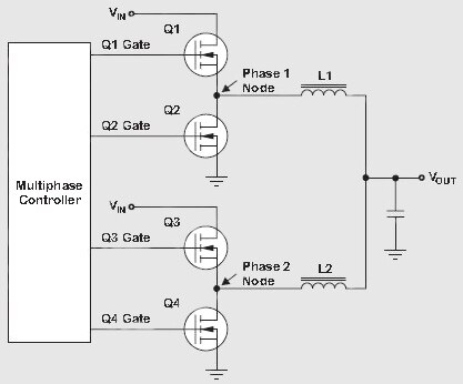
Figure 1: A typical dual-phase buck converter with associated multiphase controller.
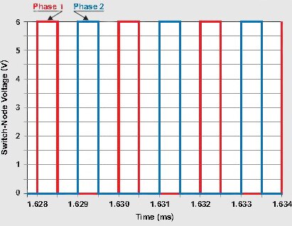
Figure 2: Waveforms for the two phases at their respective nodes show that the two phases are interleaved.
Consequently, due to reduced current in each phase, the output-filter requirements are also greatly simplified. For instance, take a 40 A converter. Unlike a 40 A single-phase design, a two-phase solution carries on an average only 20 A in the power stage of each phase. This lower average current, along with lower saturation current, results in drastically reduced output inductance and inductor size.
Another benefit of a multiphase solution is the reduced ripple voltage across the output capacitor, which is the result of ripple-current cancellation in the output-filter stage. Figure 3 illustrates the simulation results for a two-phase buck converter at a duty cycle of 25 percent. As shown, the inductor ripple current is 2.2 A, but the output capacitor sees only 1.5 A due to ripple-current cancellation. When the duty cycle is increased to 50 percent, the two-phase solution shows no ripple current in the output capacitor.
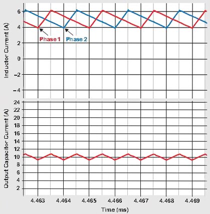
Figure 3: Simulated results show that the output ripple current is much lower at 25% duty cycle, which dramatically reduces when the duty cycle is increased.
Similarly, due to reduction of energy stored in each output inductor, the load-transient characteristics also see a boost in performance. The reduced ripple voltage, due to current cancellation, minimizes output voltage overshoot and undershoot.
To ensure that the input capacitors do not overheat, they have to be carefully selected to satisfy the ripple-current (rms) requirements. TI’s application note shows that with multiphase approach, the input ripple current (rms) specs for the input capacitors are significantly reduced. In fact, the discussion suggests that it is reduced by nearly half to easily satisfy the ripple-current (rms) demands of the buck stage.
A design example
Using the dual-phase synchronous buck controller LM3754, TI has created a high-power-density evaluation board that delivers 1.2 V at 40 A from a 12 V input supply. Measuring 2 × 2 in., the dual-phase converter switches at 300 kHz per phase. The complete schematic used to create the evaluation board is shown in Figure 4, while the operating specs for the dual-phase buck converter board are summarized in Table 1.
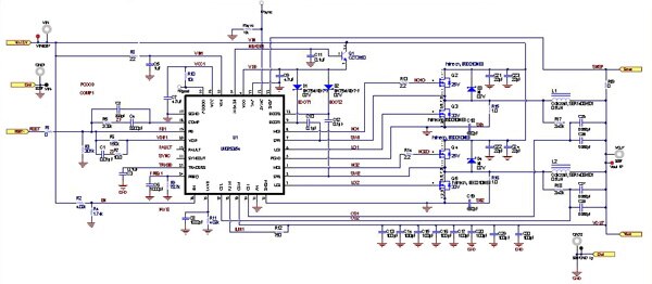
Figure 4: The complete schematic of the dual-phase converter using LM3754.
|
Input voltage |
10.8 to 13.2 V |
|
Output voltage |
1.2 V ± 1% |
|
Output current |
40 A (max) |
|
Switching frequency |
300 kHz |
|
Module size |
2 x 2 inches |
|
Circuit area |
1.4 x 1.3 inches |
|
Module height |
0.5 inches |
|
Air flow |
200 LFM |
|
Number of phases |
2 |
Table 1: Operating conditions for the LM3754 based dual-phase step-down converter.
To obtain best performance, the layout for the LM3754 evaluation board is optimized for minimal noise and voltage drops, as described in TI/National Application Note 2021.² The result is high efficiency, reduced rms ripple current, low ripple voltage, and good transient performance. Measured efficiency performance is depicted in Figure 5.
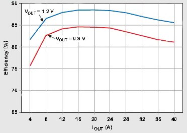
Figure 5: Measured efficiency performance of the 40-A dual-phase converter with 1.2 VDC output.
Results indicate that for a given size, the efficiency delivered by the dual-phase converter is higher than a single phase design. It remains above 80 percent from low-load to full-load, with peak performance of about 89 percent at mid-load.
Because LM3754 is a scalable dual-phase synchronous buck controller, it can be easily cascaded for achieving higher number of phases to handle higher output currents. Using two LM3754s, TI has also developed a four-phase board that delivers 1.2 VDC at 80 A from a 12 VDC input. Though the peak efficiency drops a little as compared to the two-phase circuit, it is still close to 86 percent.
For step-down regulator applications that must work from a high input voltage or a widely varying input, TI is offering LM5119. Unlike the LM3754, the LM5119 is simply a dual synchronous buck controller with an input voltage range of 5.5 to 65 V. It can be configured for dual outputs or interleaved for single output. The control method is based upon current-mode control using an emulated current ramp.
Other suppliers of multiphase buck converters include International Rectifier Corp., Intersil, Linear Technology, and Maxim Integrated Products. Aside from providing controller chips and design support for high-power multiphase step-down converters at low load voltage, these manufacturers have also created application notes based on their respective multiphase controller ICs.
References
- Application Note, “Benefits of a Multiphase Converter,” by David Baba, Applications Engineering Manager, Texas Instruments Inc.
- Application Note 2021, “LM3753/54 evaluation board,” Texas Instruments/National Semiconductor.
免责声明:各个作者和/或论坛参与者在本网站发表的观点、看法和意见不代表 DigiKey 的观点、看法和意见,也不代表 DigiKey 官方政策。


