Synchronizing Small-Scale PV Systems with the Grid
投稿人:电子产品
2015-09-24
At the heart of small-scale, grid-tied energy-harvesting systems the inverter delivers excess power to the grid during periods of high energy from ambient sources. In designing grid-tied inverters, engineers need to ensure that this excess power is tightly synchronized to the grid, typically through the use of sophisticated phase-locked loop (PLL) implementations. To meet varied synchronization challenges, engineers can create effective PLL grid-synchronization algorithms by leveraging the performance and functionality of highly-integrated MCUs and related devices from manufacturers including Analog Devices, Cypress Semiconductor, Freescale Semiconductor, Infineon Technologies, IXYS, Littelfuse, Maxim Integrated, Microchip Technology, Microsemi, NXP Semiconductors, Renesas, STMicroelectronics, and Texas Instruments.
Connected to the utility power grid, small-scale residential energy-harvesting systems offer customers the opportunity to earn credit by passing excess generated power to the grid. At the heart of these systems, grid-tied inverters are responsible for delivering this excess power seamlessly, meeting specific requirements for power quality. Among these requirements, the need for tight synchronization with grid power is paramount.
When driving power to the grid, grid-tied inverters must provide a stable, sinusoidal AC waveform that matches grid voltage and frequency according to utility standards. Poor synchronization can lead to load imbalances, damage to connected equipment, instability in the grid, and even power outages in the grid itself.
In power-utility facilities, grid synchronization relies on control of the speed of massive turbines and generator motors used to generate power. In an energy-harvesting system, however, grid synchronization relies on control of the inverter’s full-bridge output stage used to produce the required AC waveform.
In an inverter design, a DC converter powers an output stage comprising a full-bridge of high-power IGBTs such as those in the Infineon TrenchStop, IXYS GenX3, or Microsemi Thunderbolt IGBT series or SCRs such as those in the Littelfuse S6016x, NXP BT152B, or STMicroelectronics TN2015H series. By carefully controlling the operation of the DC converter and gating the bridge’s power devices, the inverter can ensure proper synchronization of the output waveform to grid voltage, frequency, and phase. In most inverter designs, a PLL provides the mechanism at the heart of this synchronization process.
In its basic form, a grid-synchronization PLL combines a phase detector (PD), filter, and voltage-controlled oscillator (VCO) (Figure 1). Here, the PLL PD compares the VCO output with the grid voltage and adjusts VCO output to match the grid.

Figure 1: In the basic phase-locked loop (PLL) structure, the phase detector (PD) synchronizes the voltage-controlled oscillator (VCO) output to the measured grid voltage, while a low-pass filter (LPF) helps reduce harmonics. (Courtesy of Texas Instruments)
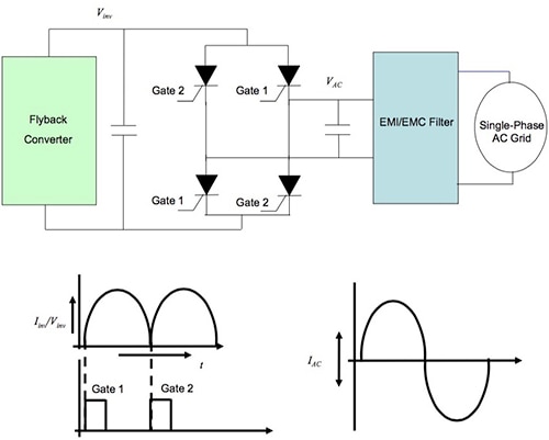
In its simplest form, a suitable PLL structure relies on a zero-crossing detector on the grid waveform and a counter to measure the time between zero crossings — adjusting inverter output as needed to match grid-voltage zero crossings (Figure 2). Designers can implement this simple PLL using a differential op amp such as the Maxim Integrated MAX9939, Microchip Technology MCP6022T, or Texas Instruments THS4121CD to trigger the next cycle of the sinusoidal output waveform from a reference sine-wave generator implemented in hardware or software.

Figure 2: By controlling the DC converter and gating the full-bridge output of an inverter, a simple phase-locked loop using a zero-crossing detection circuit can provide an AC output waveform synchronized with the grid. (Courtesy of Microchip Technology)
In practice, however, simple PLL implementations can fail to track grid voltage during startup, grid faults, and other adverse operating conditions. As a result, the topic of grid synchronization in general and suitable PLL algorithms in particular continues to be the subject of active research in academia and industry. Nevertheless, for nominal operating conditions, inverter designers have found success with a variety of sophisticated PLL algorithms that effectively enhance the functional blocks within the basic PLL structure to provide more advanced functionality.
For example, the Synchronous Reference Frame, or Direct-Quadrature, PLL (DQ PLL) augments the traditional PLL PD to shift the calculation to a synchronous rotating reference frame. Here, the PD includes a Park Transformation that performs the frame translation, reducing the grid’s three AC values to two DC values and thus simplifying the phase-detect calculations. DQ PLLs are able to achieve stable operation in most cases, even in the presence of harmonic distortions and frequency variations of the three-phase utility grid voltages. Still, this algorithm can be sensitive to voltage imbalances and errors in grid measurement.
A further refinement, the Second Order Generalized Integrator PLL (SOGI PLL), further enhances the PD functionality of the PLL structure. In a SOGI PLL, the PD detects the phase error by generating an orthogonal signal and performing a Park Transformation on the result (Figure 3). With this approach, designers can tune the orthogonal signal generator to reject other frequencies except the grid frequency. Other variations of this algorithm are capable of precise detection of the phase and frequency even in the presence of low-order harmonics close to the grid fundamental frequency.

Figure 3: More advanced PLL algorithms such as the Second Order Generalized Integrator PLL (SOGI PLL) retain the basic PLL structure while enhancing the phase detector — translating the synchronization problem to a reference frame that helps simplify synchronization calculations. (Courtesy of Texas Instruments)
Given the complexity of practical grid-synchronization algorithms, implementation of the corresponding PLL functionality relies on powerful 32-bit processors. Devices such as the Analog Devices ADUCM360 MCU combine a high-performance processor core with a full complement of peripherals needed to implement grid-synchronization units. Based on the ARM 32-bit Cortex-M3 core, the ADUCM360 integrates a pair of multichannel sigma-delta (Σ-Δ) analog-to-digital converters (ADCs), digital I/O, and Flash memory, providing the essential components of a PLL solution.
Furthermore, highly integrated MCUs such as the Analog ADUCM360, Renesas V850E, and Freescale Semiconductor MC56F8013 and MC56F8023 also include a high-resolution pulse-width modulator (PWM) that can be used to control an inverter’s DC converter and full-bridge output stage. With the Cypress Semiconductor Corp PSoC 5LP ARM Cortex-M3-based series and its configurable peripheral-block structure, designers can set the PSoC’s integrated configurable digital and analog blocks to implement a complete signal path for measuring grid current and voltage. Furthermore, designers can configure the PSoC’s on-chip PWM blocks for inverter control.
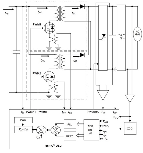
Members of the Microchip dsPiC series such as the DSPIC33EP128MC206 provide multiple independent pairs of PWMs, allowing flexible inverter-control options. Using this class of devices, designers can implement a full inverter-control subsystem for a solar-harvesting system, using embedded software routines to execute algorithms for maximum power-point tracking (MPPT) and grid-synchronization PLL functionality (Figure 4).

Figure 4: Highly integrated devices such as the Microchip Technology dsPiC series MCUs provide independent PWMs, allowing designers to independently control the DC converter and full-bridge SCR devices as needed to achieve grid synchronization. (Courtesy of Microchip Technology)
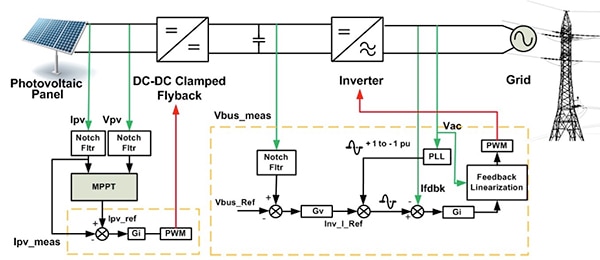
Members of the Texas Instruments C2000 C28x Piccolo series such as the Texas Instruments TMS320F28035 C2000 MCU feature TI’s enhanced PWM Modules (ePWM), providing multiple PWM channels with very-high resolution and granular control. Combined with the C2000 32-bit processor core and independent 32-bit floating-point math accelerator, these devices provide a high-performance single-chip solution for control of even complex two-stage grid-tied inverter designs (Figure 5).

Figure 5: With their combination of high-performance 32-bit processor core, independent float-point math accelerator, analog peripherals, and enhanced PWM channels, MCUs such as the Texas Instruments TMS320F28035 provide a single-chip solution for controlling the operation and output synchronization of a grid-tied inverter. (Courtesy of Texas Instruments)
Conclusion
Tight synchronization with the grid is essential for seamless delivery of excess power by grid-tied energy-harvesting systems. At the heart of grid-synchronization methods, PLL algorithms can ensure proper operation despite adverse operating conditions and even grid faults. For designers of grid-tied inverters, highly integrated MCUs with on-chip ADCs and PWMs can significantly ease the task of implementing sophisticated PLL algorithms and control mechanisms needed for effective grid synchronization.
For more information on the parts discussed in this article, use the links provided to access product pages on the DigiKey website.
免责声明:各个作者和/或论坛参与者在本网站发表的观点、看法和意见不代表 DigiKey 的观点、看法和意见,也不代表 DigiKey 官方政策。


